Method and apparatus for controlling electric servo press

a technology of electric servo press and electric servo press, which is applied in the direction of electric programme control, forging press, forging/pressing/hammering apparatus, etc., can solve the problems of mechanical press machine, disadvantageous hydraulic press in large energy loss, low productivity, etc., and achieve simple and low-cost configuration, large pressure force, and high accuracy

Inactive Publication Date: 2014-05-20
AIDA ENG LTD
View PDF14 Cites 13 Cited by
  • Summary
  • Abstract
  • Description
  • Claims
  • Application Information

AI Technical Summary

Benefits of technology

[0019]The present invention has been made in view of the aforementioned actual conditions of the related art, and therefore has an object to provide an apparatus and a method for controlling an electric servo press using a rotary-to-linear motion converting mechanism having a decentering shaft, which is capable of generating a large pressure force with a simple and low-cost configuration and is also capable of controlling a pressure force of a slide with high accuracy.

Problems solved by technology

However, the hydraulic press is disadvantageous in a large energy loss due to heating and cooling and low productivity due to a low processing speed because of the use of the hydraulic pressure.
On the other hand, the mechanical press machine (hereinafter, also referred to as “mechanical press”) has drawbacks in terms of adjustment and retention of the pressure force.
On the other hand, it is difficult to obtain a large thrust in view of the structure.
Therefore, the linear drive electric motor has difficulty in handling the permanent-magnet side unit at the time of incorporation of the permanent-magnet side unit into the press machine.
Further, it is not easy either to increase the torque by using the reducer to obtain a large thrust as in the case where the rotary electric motor is used.
H10-277797, it is difficult to obtain a large thrust due to restrictions in view of the mechanism.
As a result, there is a fear of causing the abrasion of the ball screw.
Therefore, in the actual conditions, it is difficult to employ the linear drive electric motor and the mechanism using the ball screw for a large press machine which is required to have a large pressure force.
Therefore, a method of adjusting the output torque by the control of the current of the servo motor so as to control the pressure force of the slide has a characteristic in that an error in output torque of the servo motor is amplified as the slide comes closer to BDC, which also increases an error in pressure force of the slide.
Thus, in practice, it is difficult to precisely control the pressure force only by controlling the torque of the servo motor.
As a result, load control scarcely functions in the vicinity of BDC.
Therefore, the control has low accuracy in the most frequently used area over the stroke of the slide of the press.
Accordingly, in the actual conditions, the press working with high accuracy cannot be satisfactorily realized.

Method used


Image

  • Method and apparatus for controlling electric servo press
  • Method and apparatus for controlling electric servo press
  • Method and apparatus for controlling electric servo press

Examples


operation example 1

[0103]An operation example 1 of the electric servo press according to the present invention is described.

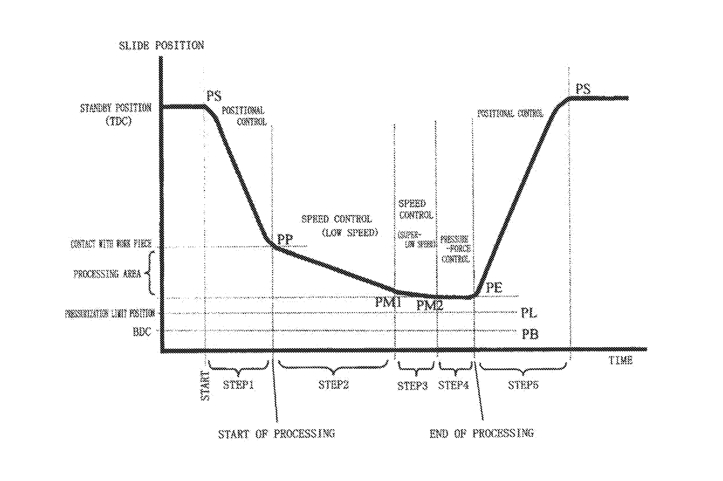
[0104]FIG. 7 illustrates a motion setting screen of a display provided to the operating section 43. In an upper part of the screen, an area for setting a designated pressure force Fm and a pressurization limit position is provided. The designated pressure force Fm is a maximum load in the processing. Specifically, a pressure force which reliably enables molding into a final shape is set as the designated pre s sure force Fm. As the pressurization limit position, the position at which the slide cannot be lowered any more in view of the structure of the dies is set. By properly setting the pressurization limit position, the dies can be prevented from being broken due to an erroneous operation or the like.

[0105]In the table on the motion setting screen illustrated in FIG. 7, data relating to the motion of the slide for each step is further set. On the screen, the data can be set for...

operation example 2

[0136]An operation example 2 according to the present invention is described referring to FIGS. 9 and 10.

[0137]The operation example 2 is an example where the pressure-force determination device 60 is more positively used. FIG. 9 illustrates an example of setting performed on the motion setting screen, and FIG. 10 illustrates the operation of the slide 13 according to the setting.

[0138]The activation is performed by pressing the start button of the electric servo press 10 as in the case of the operation example 1. The servo motor drive controller 50 starts driving the servo motor 30 under the positional control so as to drive and lower the slide 13 from the standby position PS at the speed [V1]. The speed [V1] is set high as in the case of the operation example 1 so that the time required for one processing stroke is reduced to improve the productivity.

[0139]In FIG. 9, [method] and [value] of [step shift] in Step 1 are set to [F] and [10%]. Therefore, the step shift is performed by ...


PUM

PropertyMeasurementUnit
pressure force Fmaaaaaaaaaa
pressure forceaaaaaaaaaa
pressure force Fraaaaaaaaaa

Abstract

A controller for an electric servo press includes: a press load sensor for detecting a pressure force of the slide; a pressure-force determination device for determining whether the pressure force of the slide reaches one or a plurality of different pressure-force setting values based on the one or the plurality of different pressure-force setting values and an output signal of the press load sensor, and for generating a pressure-force achievement signal each time the pressure force of the slide reaches each of the one or the plurality of different pressure-force setting values; a servo motor drive controller for controlling driving of the servo motor; and a motion command device. In response to the pressure-force achievement signal, switching of a drive control mode by the servo motor drive controller is switched, and / or a motion to be commanded by the motion command device is switched.

Description

CROSS REFERENCE TO RELATED APPLICATIONS[0001]The present application claims priority under 35 U.S.C. §119 to Japanese Patent Application No. 2009-277377, filed Dec. 7, 2009, which is incorporated herein by reference.FIELD OF THE INVENTION[0002]The present invention relates to a technology for controlling an electric servo press machine using a rotary-to-linear motion converting mechanism for converting rotary motion into linear motion through an intermediation of a decentering shaft such as a crankshaft or an eccentric shaft to convert a rotational output of a servo motor into linear motion of a slide so as to perform press working.BACKGROUND[0003]Press machines are roughly classified into two types: hydraulic press machines and mechanical press machines. The hydraulic press machines use a hydraulic pressure as a drive source to drive a slide. The mechanical press machines drive a driving mechanism (for example, a crank mechanism) with an electric motor to vertically move a slide co...

Claims


Application Information

Patent Timeline
Patent Type & Authority Patents(United States)
IPC IPC(8): B30B15/14
CPCG05B19/19B23Q15/18B30B15/148B30B15/0094
Inventor SENDA, MASAKIYOSHIDA, HIROAKIHARADA, AKIRAHISHINUMA, KOICHIKAWABUCHI, HIROKAZUMATSUDA, HIDEYUKIHARADA, YASUHIROHONJO, KAZUKI
Owner AIDA ENG LTD
Why Eureka
Try Eureka