Mounting structure of a power unit for a utility vehicle

a technology for power units and utility vehicles, applied in the direction of electric propulsion mounting, jet propulsion mounting, transportation and packaging, etc., can solve the problems of degrading the ride quality of the vehicle, and achieve the effect of enhancing the mounting strength

Active Publication Date: 2014-05-20
KAWASAKI MOTORS LTD
View PDF20 Cites 29 Cited by
  • Summary
  • Abstract
  • Description
  • Claims
  • Application Information

AI Technical Summary

Benefits of technology

[0019]With the above configuration, the power unit is mounted to the chassis frame at three points, th

Problems solved by technology

However, when the chassis frame vertically vib

Method used


Image

  • Mounting structure of a power unit for a utility vehicle
  • Mounting structure of a power unit for a utility vehicle
  • Mounting structure of a power unit for a utility vehicle

Examples


Embodiment Construction

Embodiments of the Invention

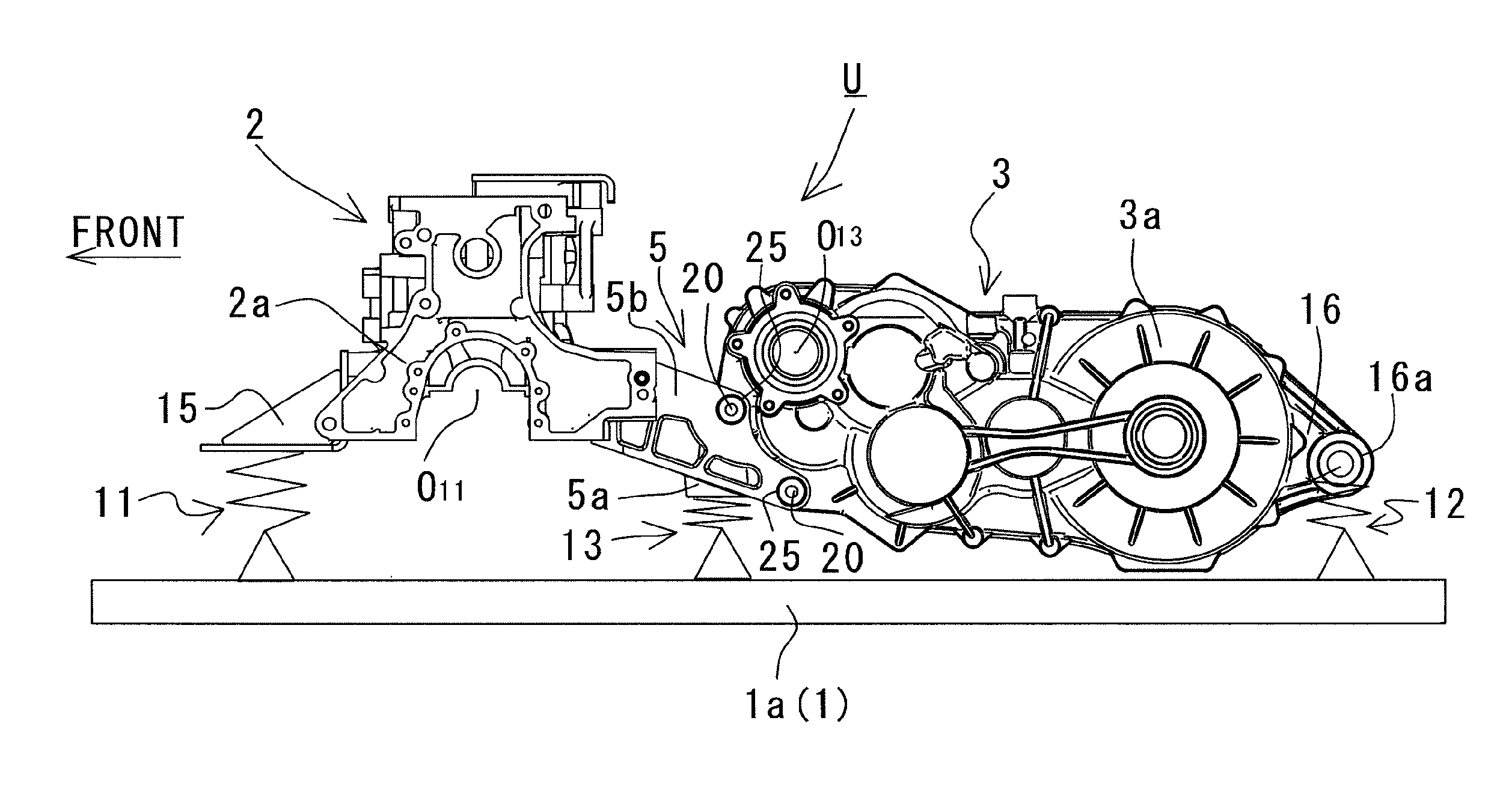
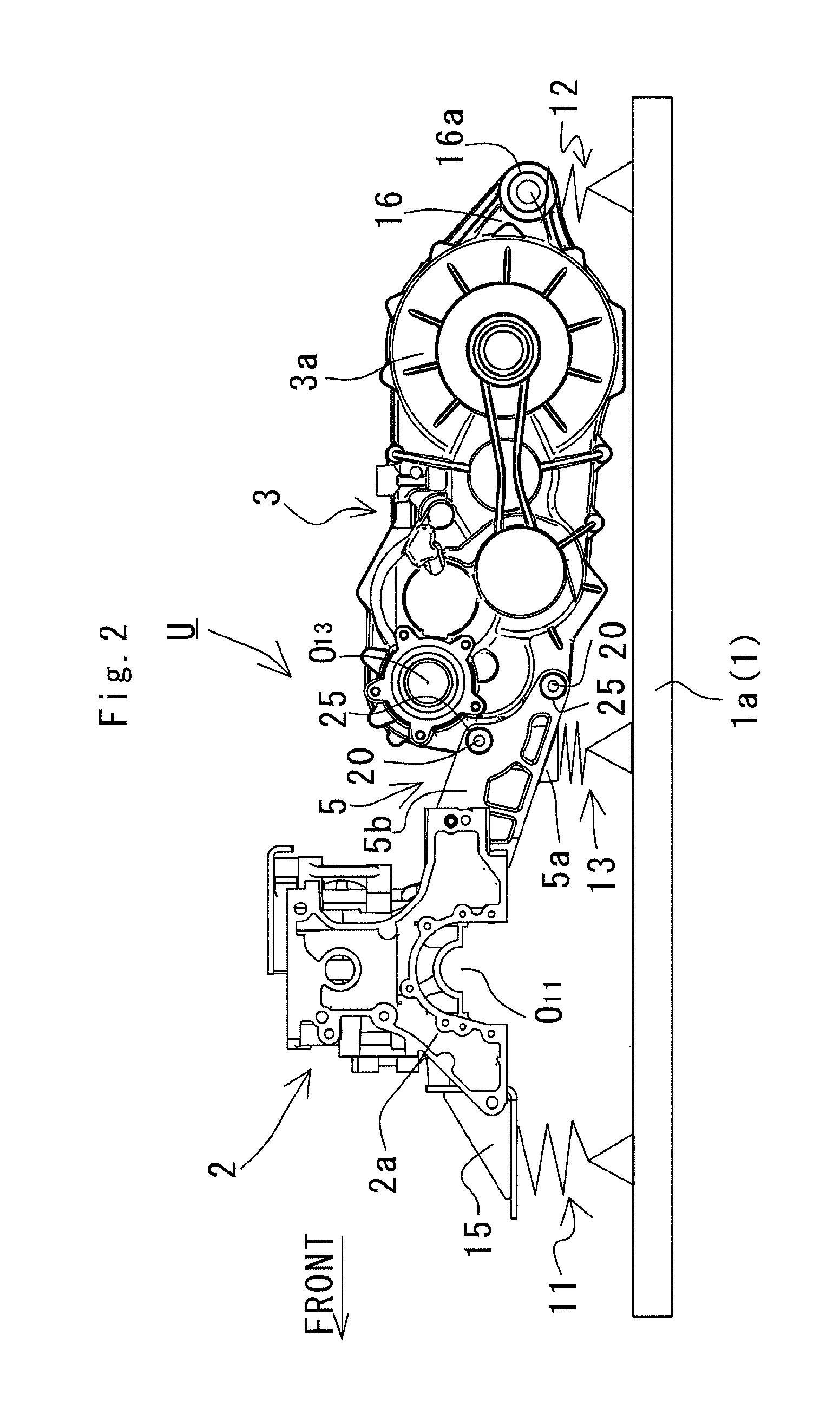
[0035]FIGS. 1 to 15 show a power unit for a utility vehicle according to the present invention. A description will be given of one embodiment according to the present invention with reference to the attached drawings. For the sake of convenience of explanation, in the following descriptions, the lengthwise direction of a utility vehicle is referred to as the lengthwise direction of an engine and other component parts; and the right and left viewed from a passenger riding in the utility vehicle (the right and left viewed from behind the vehicle) in a vehicular widthwise direction are referred to as the right and left of the vehicle, the engine, and the other component parts.

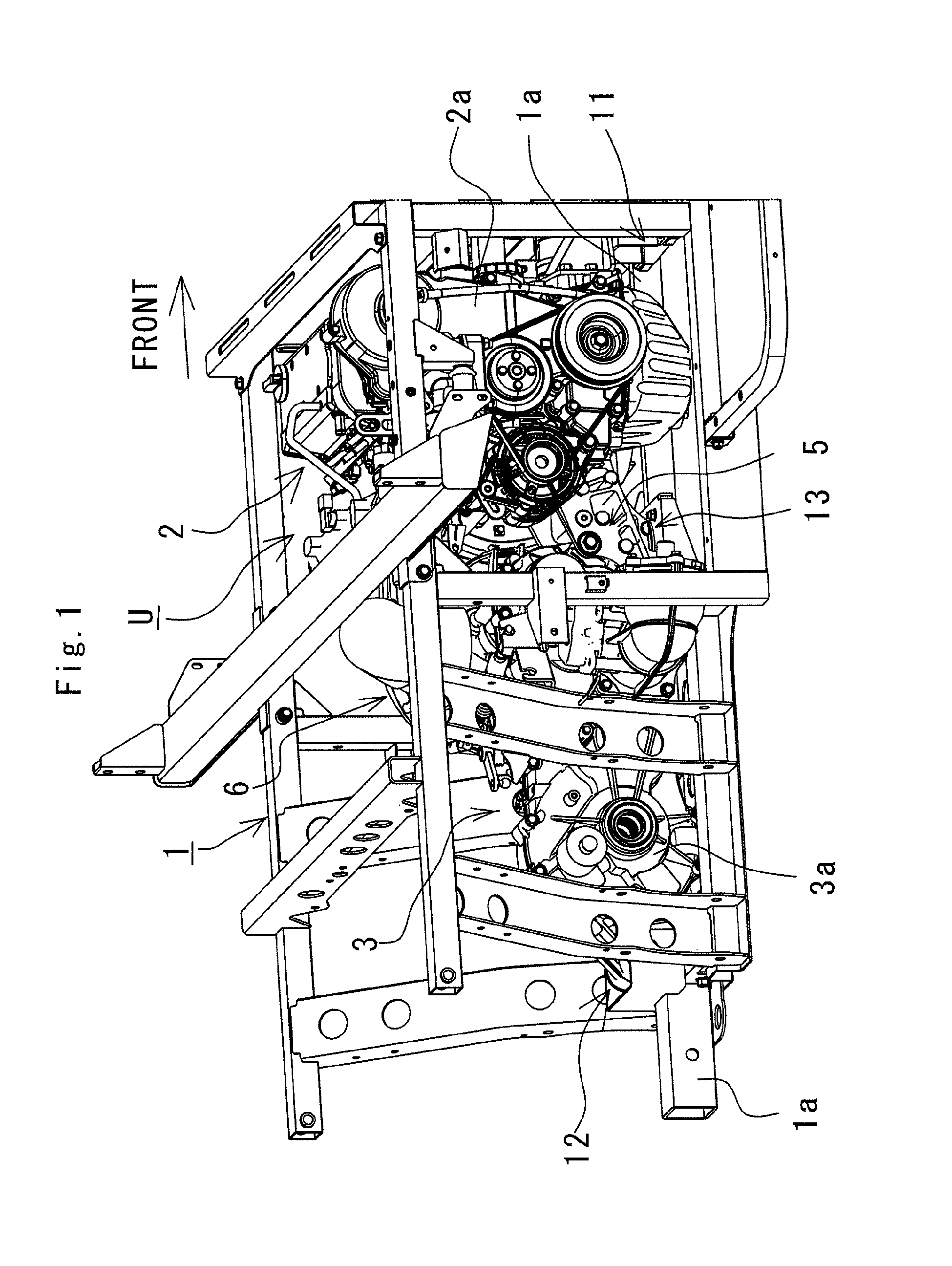
[0036]FIG. 1 is a perspective view showing a power unit U, wherein a chassis frame 1 is constituted of a plurality of frame members and formed into a substantially rectangular shape being elongated in a vehicular lengthwise direction. The power unit U is disposed at a rear portion of th...


PUM


Abstract

In a mounting structure of a power unit for a utility vehicle, the power unit includes an engine and a transmission coupled onto one side of the engine in a vehicular lengthwise direction. A lower end substantially at the center of the engine in a vehicular widthwise direction and a lower end substantially at the center of the transmission in the vehicular widthwise direction are mounted to an upper surface of a chassis frame by a front mounting mechanism with a damper and a rear mounting mechanism with a damper.

Description

BACKGROUND OF THE INVENTION[0001]1. Field of the Invention[0002]The present invention relates to a mounting structure of a power unit for a utility vehicle including an engine and a transmission connected onto one side of the engine in a lengthwise direction of a vehicle.[0003]2. Description of the Related Art[0004]Examples of a structure of a power unit for a utility vehicle include a structure in which a transmission is formed independently of an engine and a structure in which a transmission is molded integrally with a crank case for an engine. In the structure in which a transmission is formed independently of an engine, for example, the engine and the transmission are securely arranged on a sub frame in a vehicular lengthwise direction. Then, the sub frame is fixed to a chassis frame via a damper.[0005]Conventionally, in any mounting structure for mounting a power unit onto a chassis frame, a plurality of mounting portions having a width over the substantially entire width of t...

Claims


Application Information

Patent Timeline
IPC IPC(8): B60K5/12
CPCB60Y2200/22B60Y2200/41B60K5/1216B60K5/04B60K5/12
Inventor YAMAMOTO, TERUAKIYAMASAKI, AKIYUKI
Owner KAWASAKI MOTORS LTD
Why Eureka
Try Eureka