Beam transport system for a hadron therapy facility

a beam transport system and hadron technology, applied in the field of beam transport system for hadron therapy facilities, can solve the problems of high investment cost of a hadron therapy facility, requiring as much optimization of patient throughput, and requiring 2 minutes of available time, so as to reduce waiting time, increase patient throughput, and increase the effect of voltag

Active Publication Date: 2014-05-20
ION BEAM APPL
View PDF2 Cites 0 Cited by
  • Summary
  • Abstract
  • Description
  • Claims
  • Application Information

AI Technical Summary

Benefits of technology

[0013]Such a discharge accelerating circuit accelerates the decay of the current induced in the electromagnet coil and thereby the decay of the residual electromagnetic field in the switching electromagnet that is de-energised. Accelerating the decay of the electromagnetic field of a de-energised switching electromagnet substantially reduces the waiting time for safely re-injecting the hadron beam into the beam transport system. Hence, the time during which a hadron beam can be effectively used in a multi-station hadron beam therapy facility is increased, which allows for an increased patient throughput.
[0025]In a preferred embodiment of the beam transport system, the power source has a voltage output adjustable between a maximum value and a steady state value; the beam transport system further includes a controller setting the voltage of the power source to its maximum value when the power source is newly connected to one of the electromagnet coils and reduces it to its steady state value as soon as the current in the electromagnet coil reaches its steady state value. This solution allows for reducing—at relatively low costs—the time necessitated for building up the required electromagnetic field in a switching magnet.

Problems solved by technology

High investment costs of a hadron therapy facility require optimizing patient throughput as much as possible.
This means however that—in average—only 2 minutes are available for switching the hadron beam from one treatment station to the other and for performing the irradiation itself.
As the electromagnetic energy stored in the switching electromagnet is quite high and the characteristic R / L of the closed discharge circuit is quite low, the decay of the current in the circuit is rather slow.
Accelerating the decay of the electromagnetic field of a de-energised switching electromagnet substantially reduces the waiting time for safely re-injecting the hadron beam into the beam transport system.
This solution allows most probably for achieving the best results in terms of discharge acceleration, but necessitates an auxiliary power source, which may not be the most cost efficient solution.
However, as the power to be absorbed in the Zener diode is rather high, it is presently rather difficult to find a suitable Zener diode at reasonable costs.

Method used


Image

  • Beam transport system for a hadron therapy facility
  • Beam transport system for a hadron therapy facility
  • Beam transport system for a hadron therapy facility

Examples


first embodiment

[0017]the discharge accelerating circuit comprises a power source capable of generating an electromotive force opposing the counter electromotive force induced in the electromagnet coil when the energisation of the electromagnet coil is interrupted. This solution allows most probably for achieving the best results in terms of discharge acceleration, but necessitates an auxiliary power source, which may not be the most cost efficient solution.

second embodiment

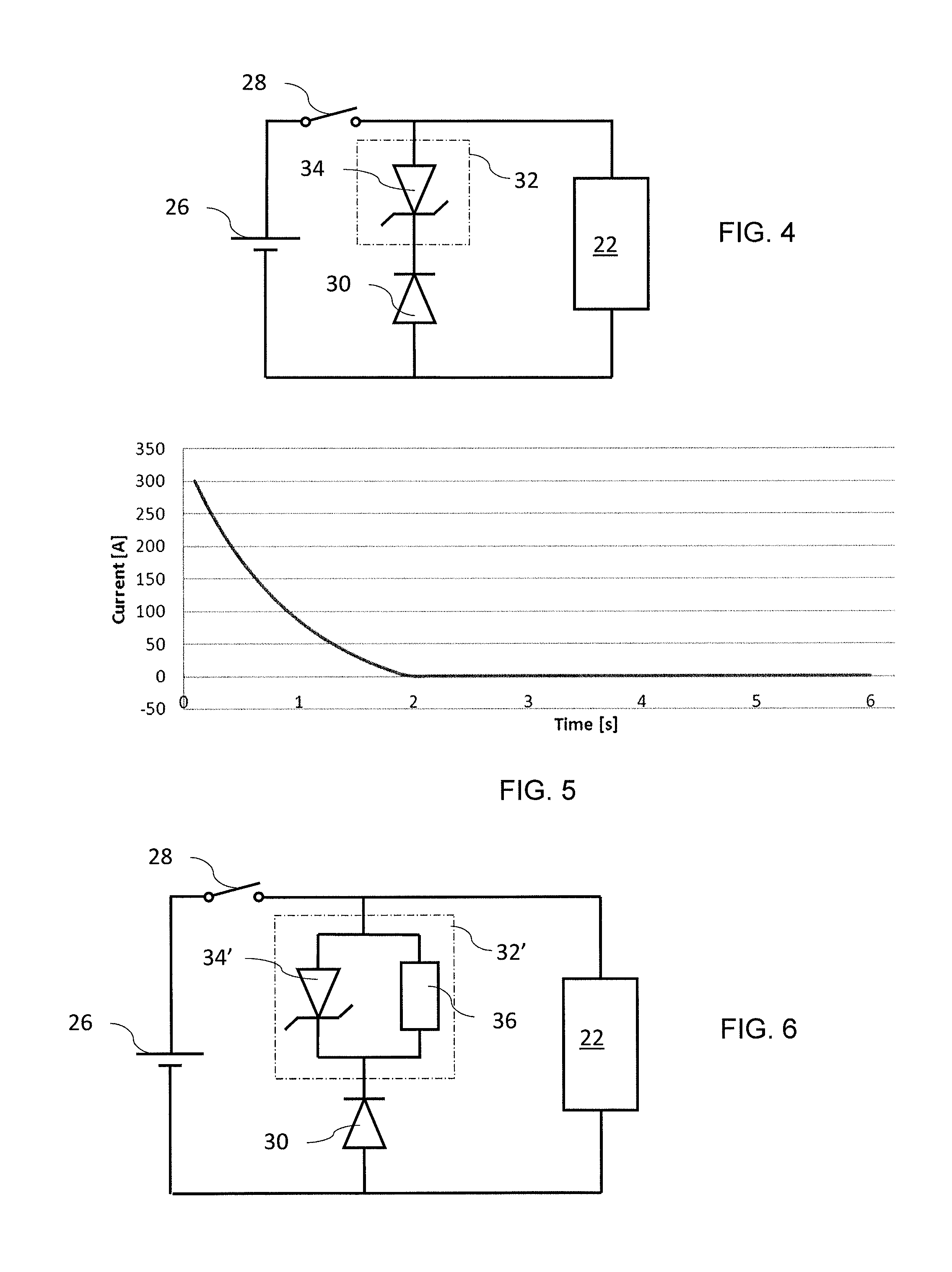
[0018]the discharge accelerating circuit comprises a Zener diode, wherein the breakdown voltage of the Zener diode opposes the counter electromotive force induced in the electromagnet coil when the energisation of the electromagnet coil is interrupted. This solution allows for achieving good results in terms of discharge acceleration if the breakdown voltage of the Zener diode is sufficiently high. However, as the power to be absorbed in the Zener diode is rather high, it is presently rather difficult to find a suitable Zener diode at reasonable costs.

[0019]It may be of advantage if the discharge accelerating circuit comprises at least two Zener diodes mounted in parallel or in series. These solutions allow for reducing the power to be absorbed in a single Zener diode. The parallel solution is generally preferred. For the serial solution, it must be possible to replace a Zener diode with a breakdown voltage VDZ with n Zener diodes with a reduced breakdown voltage of VDZ / n.

third embodiment

[0020]the discharge accelerating circuit further comprises a current sensitive bypass circuit mounted in parallel with the Zener diode, respectively the Zener diodes, the current sensitive bypass circuit bypassing the decay current around the Zener diode, respectively the Zener diodes, until this current drops below a certain value. In this solution the current sensitive bypass circuit is used to “start” the Zener diode(s) only when the current induced in the electromagnet coil has already dropped below a certain value. Thereby the Zener diode has to absorb a reduced power in comparison to a Zener diode through which the initial decay current flows.

[0021]A further embodiment of the discharge accelerating circuit comprises: a first circuit including a first Zener diode and a first current sensitive bypass circuit mounted in parallel with the first Zener diode, wherein the first current sensitive bypass circuit bypasses the decay current around the first Zener diode until this decay c...


PUM


Abstract

A beam transport system for a hadron therapy facility comprises: a main beam transport line; secondary beam transport lines branching off from the main beam transport line for delivering the hadron beam into the patient treatment stations; and switching electromagnets for deviating the hadron beam from the main beam transport line into the secondary beam transport line. A discharge circuit associated with each switching electromagnet comprises a discharge accelerating circuit capable of generating a voltage opposing the counter electromotive force induced in the electromagnet coil of the switching electromagnet when the energization of the electromagnet coil producing the hadron beam deviation is interrupted, wherein this voltage stays substantially constant or increases as the current induced in the electromagnet coil decreases.

Description

CROSS-REFERENCE TO RELATED APPLICATION[0001]This application is based upon and claims the benefit of priority from prior European Application No. 12178382.3 filed on Jul. 27, 2012, the entire contents of which are incorporated herein by reference.DESCRIPTION OF THE INVENTION[0002]1. Technical Field[0003]The present invention generally relates to a hadron therapy facility. It relates more particularly to a beam transport system for such a hadron therapy facility with at least two patient treatment stations.[0004]2. Background Art[0005]High investment costs of a hadron therapy facility require optimizing patient throughput as much as possible. A modern hadron therapy facility typically includes several patient treatment stations, which are successively supplied with a hadron beam generated in a common hadron accelerator. If it takes e.g. 10 minutes for correctly positioning a patient in a treatment station, the throughput of a hadron therapy facility with a single treatment station wo...

Claims


Application Information

Patent Timeline
Patent Type & Authority Patents(United States)
IPC IPC(8): A61N5/00G21G5/00
CPCA61N5/1048A61N2005/1087A61N2005/1074A61N5/1079
Inventor CLAEREBOUDT, YVESWILCZAK, CHRISTOPHEBOGAERT, DANIEL
Owner ION BEAM APPL
Why Eureka
Try Eureka