Hip fracture device with static locking mechanism allowing compression

a technology of a locking mechanism and a hip fracture, which is applied in the field of appendix and method for the treatment of proximal femur fractures, can solve the problems that the bone plate system cannot be used to compress the fracture site, and achieve the effects of preventing the shortening of the femoral neck, improving postoperative function of the hip, and providing compression and angular and rotational stability

Active Publication Date: 2014-05-27
STRYKER EURO OPERATIONS HLDG LLC
View PDF165 Cites 7 Cited by
  • Summary
  • Abstract
  • Description
  • Claims
  • Application Information

AI Technical Summary

Benefits of technology

[0009]The present invention provides a bone plate for use with fractures of the femur. Screws attach the bone plate to the femur. The compression screws that are inserted in the neck of the femur may be parallel to the axis of the neck of the femur. Inserting the bone screws in the neck region of the femur provides compression and angular and rotational stability to the head of the femur. Cortical interlocking type screws may be used in a distal portion of the bone plate in the subtrochantric shaft region of the femur. The compression screws stabilize bone fragments when used with end caps and prevent the shortening of the femoral neck resulting in improved postoperative function of the hip. The end cap may be inserted in a threaded plate hole and contact the top of each screw. A polymer buffer may be placed in the screw hole between the end cap and the head of the compression screw. The polymer buffer may allow small movement of the screw.
[0010]In use, the compression bone screw is inserted in the screw hole and screwed into the neck of the femur until the underside of the bone screw sits on the flat face formed in screw hole. Next, the screw is rotated further to apply compression to the fracture site. Once the desired amount of compression is applied, the end cap is inserted in screw hole. The end cap prevents the screw from moving back in the axial direction.
[0012]In use, the screw and the split locking ring are assembled together and inserted into the screw hole. The assembly of the screw and the locking ring is then screwed into the bone using a dedicated insertion instrument that holds and rotates the screw and the locking ring simultaneously. When the head of the screw reaches the terminal axial position in the screw hole, both the screw and the locking ring can be rotated further to apply compression to the fracture site. After the compression is applied, the screw alone is turned. The locking ring is thereby clamped between the head of screw and the bone plate. This results in fixing the screw in place such that the screw can not back out in axial direction.
[0017]In yet another aspect, a bone plating system includes a bone plate having a plurality of openings and at least one bone screw capable of being received through the opening and into a bone. The bone screw having a head adapted for fitting in the opening when the bone screw is fully inserted in the bone, the head of the bone screw and the opening in the bone plate having complementary shape such that the bone screw when seated in the opening has angular stability. At least one end cap is fixedly inserted in the opening, and a layer of polymeric material is interposed between the end cap and the top of the head such that the compression of the polymeric material would allow slight axial movement of the screw.

Problems solved by technology

However, such bone plate system cannot be used to compress the fracture site.

Method used


Image

  • Hip fracture device with static locking mechanism allowing compression
  • Hip fracture device with static locking mechanism allowing compression
  • Hip fracture device with static locking mechanism allowing compression

Examples


Embodiment Construction

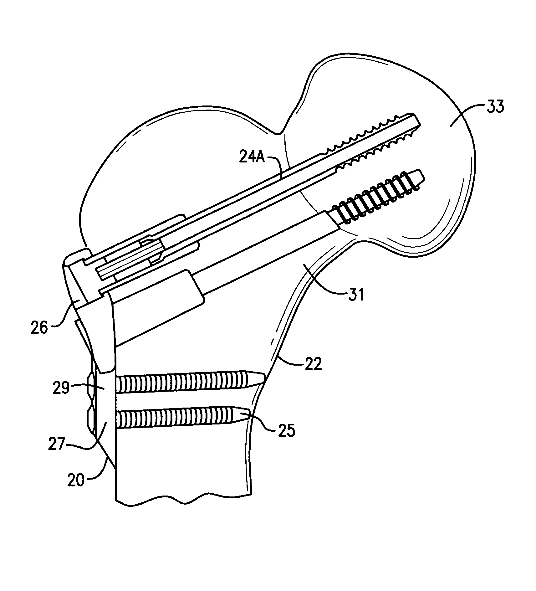
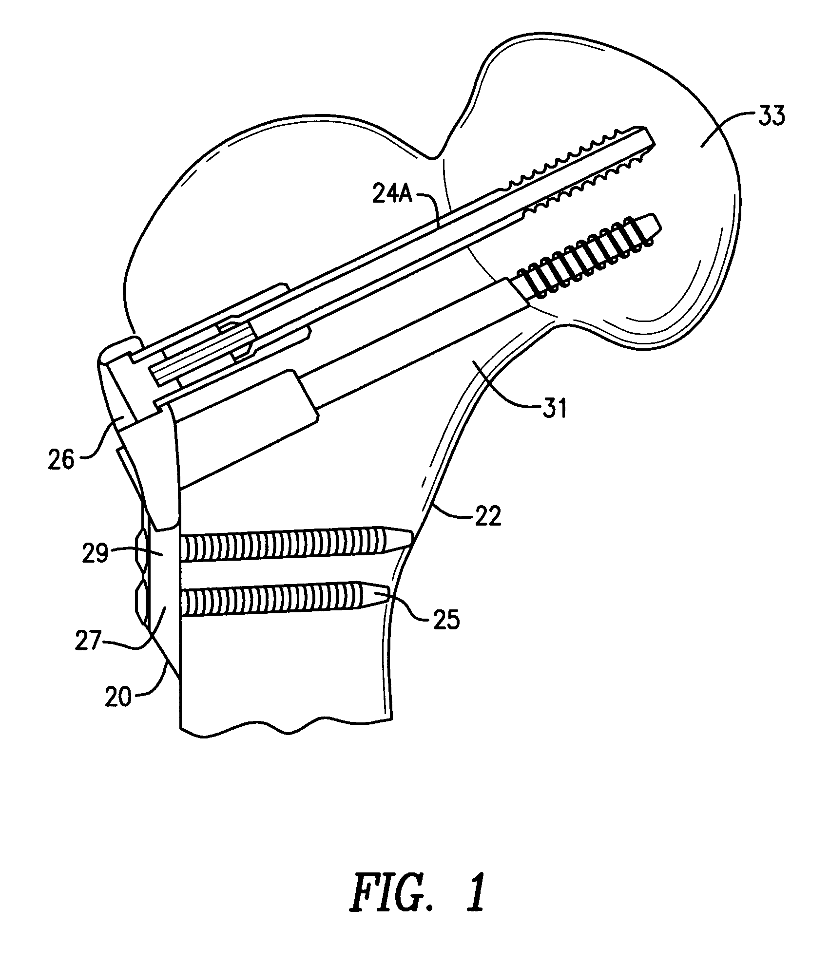
[0027]FIG. 1 shows a bone plate 20 mounted on a femur 22. Any one of the compression screws disclosed hereafter may be used with the bone plate 20. In FIG. 1, compression screws 24A attach the bone plate 20 to the head 33 and neck 31 of femur 22. Screws 24A may be used to attach bone plate 20 to the femur via screw holes 26 in plate 20. Cortical screws 25 may be used to attach a distal portion 27 of bone plate 20 to the subtrochantric shaft of the femur 22. In the preferred embodiment these are locking screws. The compression screw 24A may provide angular and axial stability to the fractured bone pieces. The compression screws 24A may be cannulated or non-cannulated. The compression screws 24A may also provide rotational stability. Rotational stability may be achieved by inserting at least two compression screws 24A through the screw holes 26 and into the neck 31 of the femur 22. The compression screws 24A that are inserted in the neck 31 of the femur 22 may be parallel to the axis ...


PUM


Abstract

A bone plate having a plurality of openings for receiving a compression bone screw or a cortical screw. An end cap, threadably insertable in the opening and having a layer of polymeric material interposed between the end cap and the top of the head such that the compression of the polymeric material would allow slight axial movement of the screw. Alternatively, a locking ring adapted to attach to the head of the screw and having shape complimentary to the features formed on the head. The locking ring and the bone screw being assembled together and being insertable in the bone simultaneously using a dedicated instrument. Compression may be applied to a bone fracture by turning the bone screw alone after the locking ring has reached its final axial position.

Description

CROSS-REFERENCE TO RELATED APPLICATION[0001]This application claims the benefit of the filing date of U.S. Provisional Patent Application No. 60 / 925,457 filed Apr. 19, 2007, the disclosure of which is hereby incorporated herein by reference.BACKGROUND OF THE INVENTION[0002]1. Field of the Invention[0003]The present invention relates generally to an apparatus and method for the treatment of fractures of the proximal femur including the neck of the femur and the intertrochantric region.[0004]2. Brief Description of the Prior Art[0005]In treatment of the fracture of the femoral neck it is necessary to maintain angular stability of the head fragment to maintain an anatomical reduction postoperatively. It is also desirable to compress fracture site intra-operatively and then to stabilize the bone fragments by not allowing any further axial or angular movement. Since axial movement of the bone fragment resulting in shortening of the neck of the femur will result in reduced physical functi...

Claims


Application Information

Patent Timeline
Patent Type & Authority Patents(United States)
IPC IPC(8): A61B17/04A61B17/70
CPCA61B17/8685A61B17/8042A61B17/746A61B17/74
Inventor SIMON, BERNDKEMPER, JAKOBHOFFMANN, CARSTEN
Owner STRYKER EURO OPERATIONS HLDG LLC
Why Eureka
Try Eureka