
Power source system for electric powered vehicle and control method thereof

a power source system and electric vehicle technology, applied in the direction of capacitors, electric devices, battery/cell propulsion, etc., can solve the problem of vehicles not being able to run, and achieve the effect of suppressing power consumption and normal vehicle activation performan

Active Publication Date: 2014-05-27
TOYOTA JIDOSHA KK
View PDF11 Cites 21 Cited by
  • Summary
  • Abstract
  • Description
  • Claims
  • Application Information

AI Technical Summary

Benefits of technology

This solution ensures normal vehicle activation performance by suppressing power consumption during stops and performing charging control of the auxiliary battery, maintaining its voltage and preventing capacity reduction, thus ensuring reliable vehicle startup even after extended periods of inactivity.

Problems solved by technology

Further, when voltage is reduced due to reduction in a remaining capacity of the low-voltage battery, the controller cannot be operated normally, and thereby there is a possibility that the vehicle cannot run even if the remaining capacity of the high-voltage battery is ensured.

Method used


Image

  • Power source system for electric powered vehicle and control method thereof
  • Power source system for electric powered vehicle and control method thereof
  • Power source system for electric powered vehicle and control method thereof

Examples


Embodiment Construction

[0035]In the following, an embodiment of the present invention will be described in detail with reference to the figures. In the following, the same or corresponding portions in the figures are denoted by the same reference characters and, basically, description thereof will not be repeated.

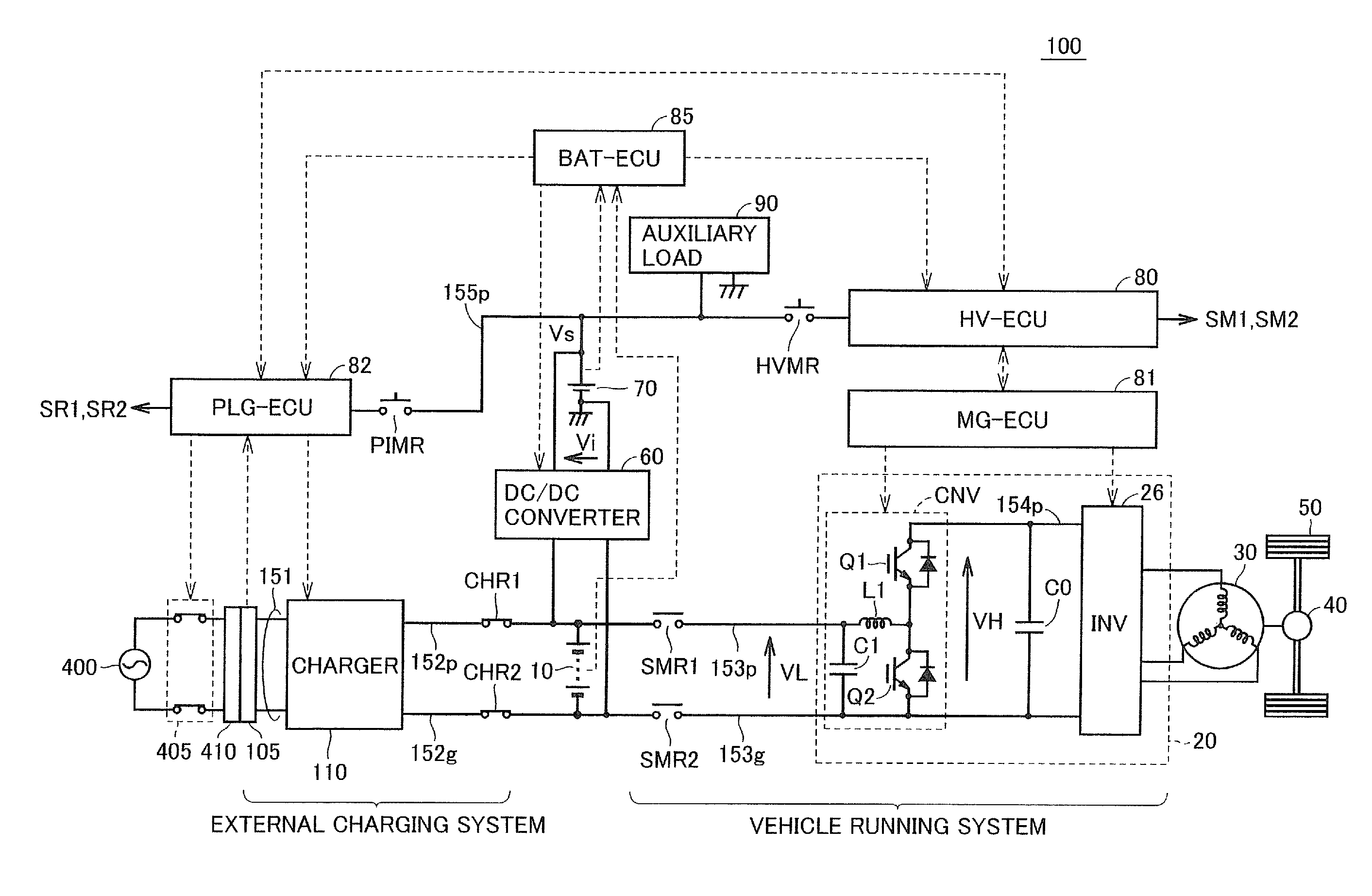
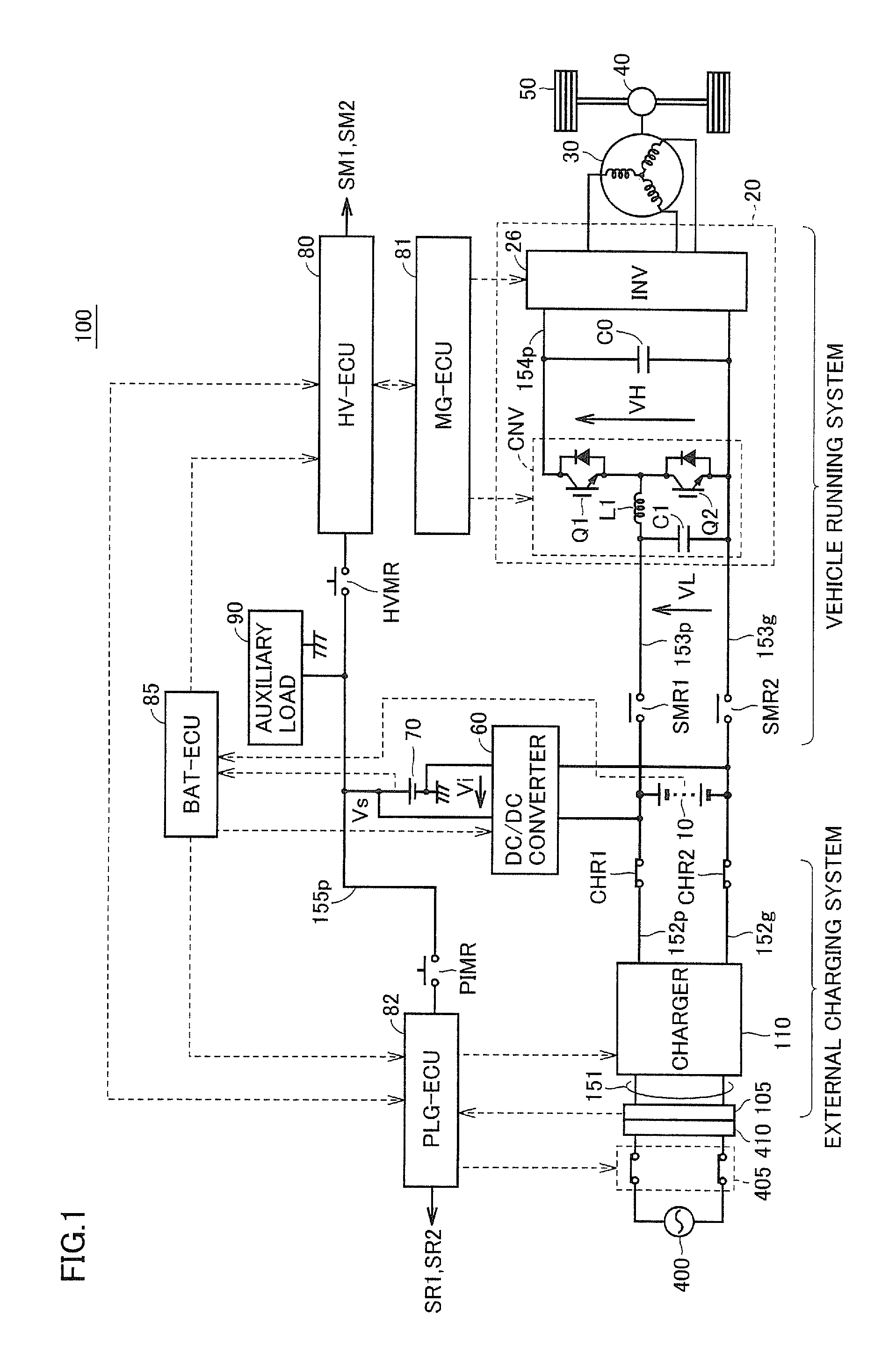
[0036]FIG. 1 is a block diagram showing a configuration of a power source system for an electric powered vehicle in accordance with an embodiment of the present invention.

[0037]Referring to FIG. 1, an electric powered vehicle 100 includes a main battery 10, a power control unit (PCU) 20, a motor generator 30, a power transmission gear 40, driving wheels 50, and a controller composed of a plurality of ECUs.

[0038]As the ECUs constituting the controller, FIG. 1 illustrates an HV-ECU 80 for controlling operation of electric powered vehicle 100 while the vehicle is running, an MG-ECU 81 for controlling operation of PCU 20, a PLG-ECU 82 for controlling external charging operation, and a BAT-ECU 85 for ...


PUM


Abstract

An electric powered vehicle is equipped with a main battery for storing electric power input to and output from a motor, and an auxiliary battery as a power source for an auxiliary system including a control system. A DC / DC converter converts an output voltage of the main battery to a level of an output voltage of the auxiliary battery. During operation, a BAT-ECU monitors states of charge of the main battery and the auxiliary battery and controls operation / stop of the DC / DC converter. When the electric powered vehicle is in a key-off state (running stop state), the BAT-ECU is intermittently operated, while an external charging system and a vehicle running system are stopped.

Description

TECHNICAL FIELD[0001]The present invention relates to a power source system for an electric powered vehicle and to a method for controlling the same. More specifically, the present invention relates to auxiliary battery charging control in an electric powered vehicle equipped with a main power storage device (main battery) for supplying electric power to a traction motor and a sub power storage device (auxiliary battery) for supplying electric power to auxiliary machines including a controller.BACKGROUND ART[0002]Electric vehicles, hybrid vehicles, and fuel cell vehicles have been known as electric powered vehicles configured such that a traction motor generating vehicle driving power can be driven using electric power from a vehicle-mounted power storage device represented by a secondary battery. An electric powered vehicle is generally configured to have two types of power storage devices, that is, a high-voltage power storage device (main battery or high-voltage battery) used to ...

Claims


Application Information

Patent Timeline
Patent Type & Authority Patents(United States)
IPC IPC(8): B60L3/00H02G3/00B60L1/00B60L50/16
CPCY02T90/14B60L2220/14B60L11/1803B60L2210/10Y02T10/7088B60L2250/10B60L11/005Y02T10/7005B60L11/14Y02T10/7216B60L11/1816Y02T90/121Y02T90/127Y02T10/7077Y02T10/7022Y02T10/70Y02T10/7072B60L53/14B60L50/40B60L50/16B60L50/51Y02T10/72Y02T90/12
Inventor MASUDA, TOMOKAZUKAMAGA, RYUICHI
Owner TOYOTA JIDOSHA KK
Learn More