Broadband linearization module and method

a linearization module and wideband technology, applied in the direction of amplifiers, amplifiers with semiconductor devices/discharge tubes, amplifiers, etc., can solve the problems of linearity deviation, undesired energy, etc., and achieve the effect of most of these techniques

Active Publication Date: 2014-05-27
EMPOWER RF SYST
View PDF7 Cites 15 Cited by
  • Summary
  • Abstract
  • Description
  • Claims
  • Application Information

AI Technical Summary

Problems solved by technology

Deviations from linearity are manifest by spectral distortion components in the output of these amplifiers—that is, undesired energy, not contained in the original signal, inside or outside the frequency band of interest.
Most of these techniques, however, are useful only in circumstances where the input signals occupy low-percentage bandwidths (typically 10% or less) or do not change frequency rapidly over time.
Moreover, digital signal processors, ASICS or FPGAs used in DPD-based designs tend to be limited in bandwidth (due to their clock frequencies) and processing capacity.
Current analog pre-distortion techniques are likewise limited in bandwidth and require adjustment when the input signal center frequency is changed.
Adaptive linearization can eliminate the limitations to the change in the center frequency of these designs, but tend to be slow to respond to changes in system characteristics and can be very complex to implement.
Feed-forward linearization techniques are also complex to implement (often making them unsuitable for use with existing amplifiers), are limited in bandwidth and often do not provide significant gains in efficiency because of the relatively high power consumption of the error or auxiliary amplifier.
Other conventional linearization solutions, such as power back-off schemes, envelope elimination and restoration designs, linear amplification using nonlinear components, and Cartesian feedback designs all have their own limitations as well.
In addition, the increasing complexity of semiconductor-based power amplifiers has memory effect or inertia and therefore limits the use of converging linearization techniques in frequency hopping applications due to the reaction time to correct.

Method used


Image

  • Broadband linearization module and method
  • Broadband linearization module and method
  • Broadband linearization module and method

Examples


Embodiment Construction

[0015]The present invention recognizes a need for improved systems and methods to linearize a power amplifier. In some embodiments, the systems and method are used where the input signal's frequency bandwidth is large (e.g., approximately one octave) and / or where the transmitting frequency can vary within its permissible range (e.g., frequency hopping). Changes in the transmitting frequency usually happen faster than conventional linearization circuits can react.

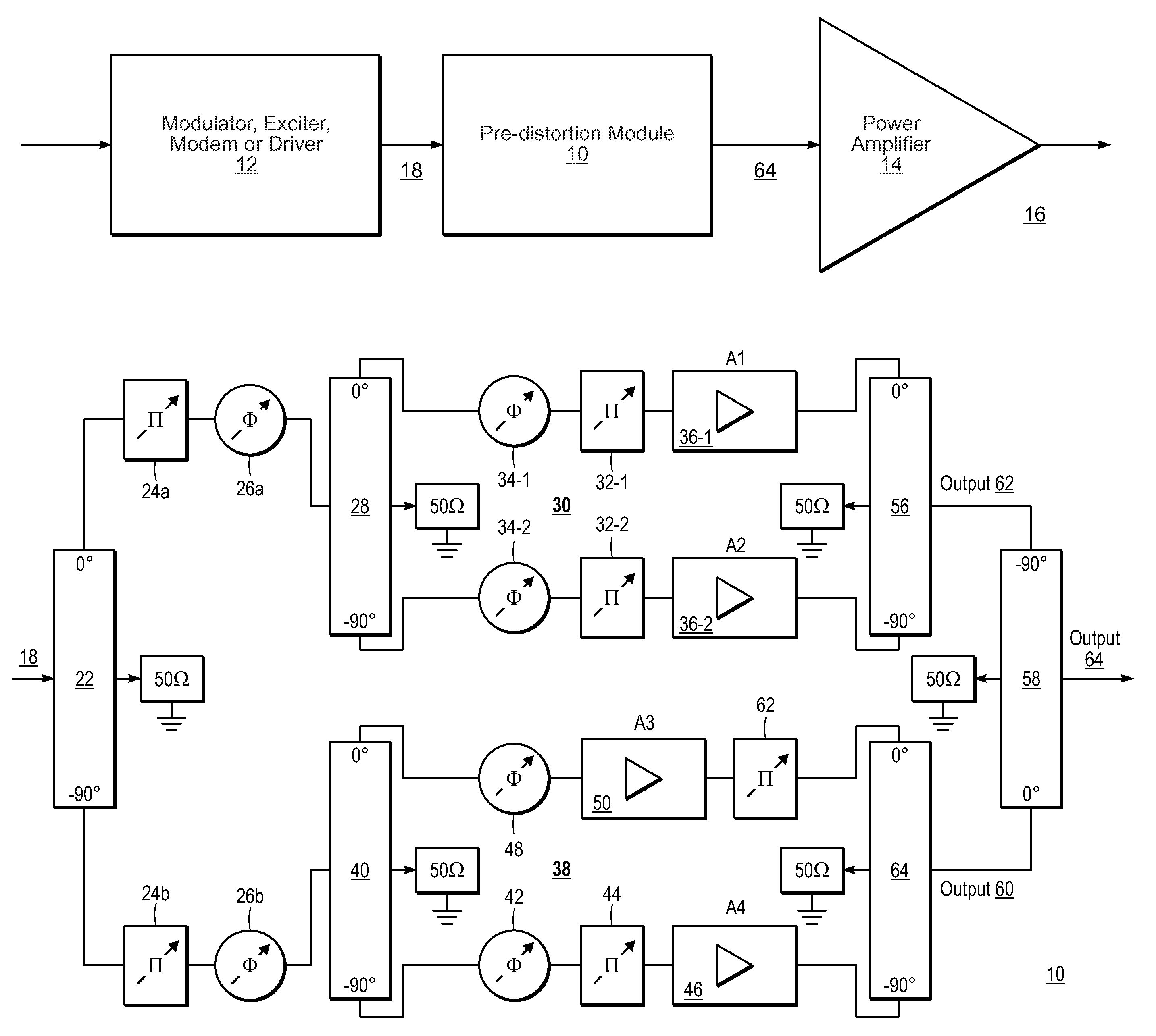
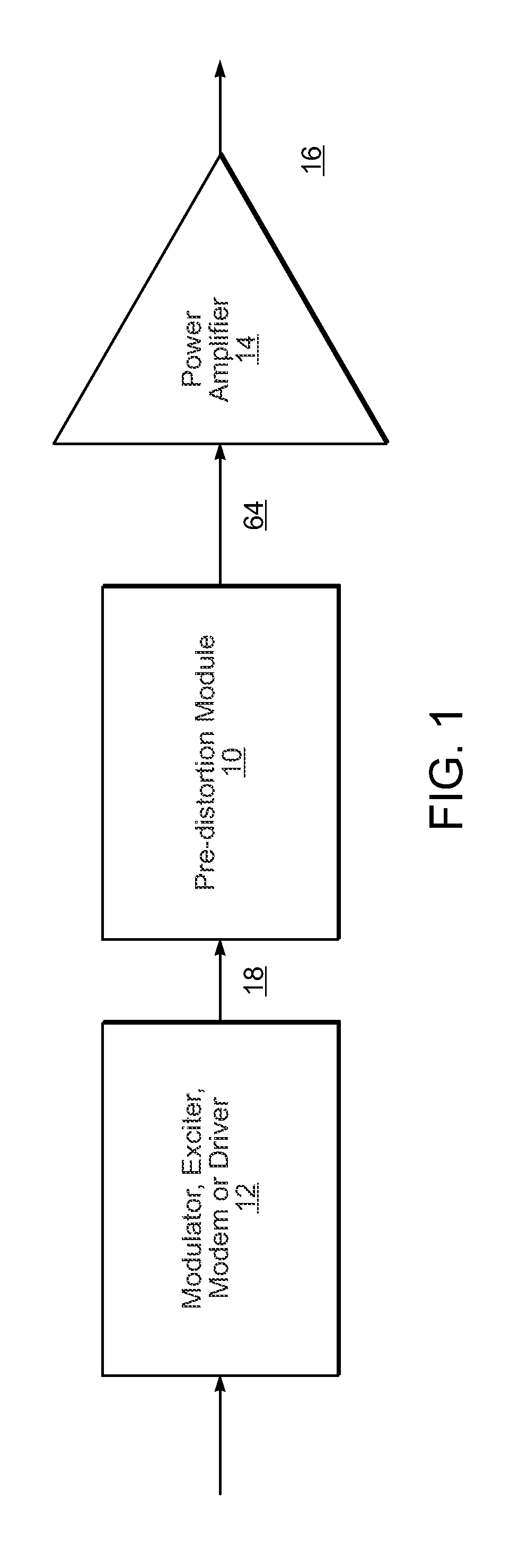
[0016]To address this need, in one embodiment, the invention is a linearization system and method that has the same bandwidth and reaction time as the power amplifier which it intends to correct. FIG. 1 is a block diagram showing the placement of a pre-distortion module 10 configured in accordance with an embodiment of the present invention in the radio frequency (RF) chain 16 of a transmitter between a modulator, exciter, modem or driver circuit 12 and a power amplifier 14.

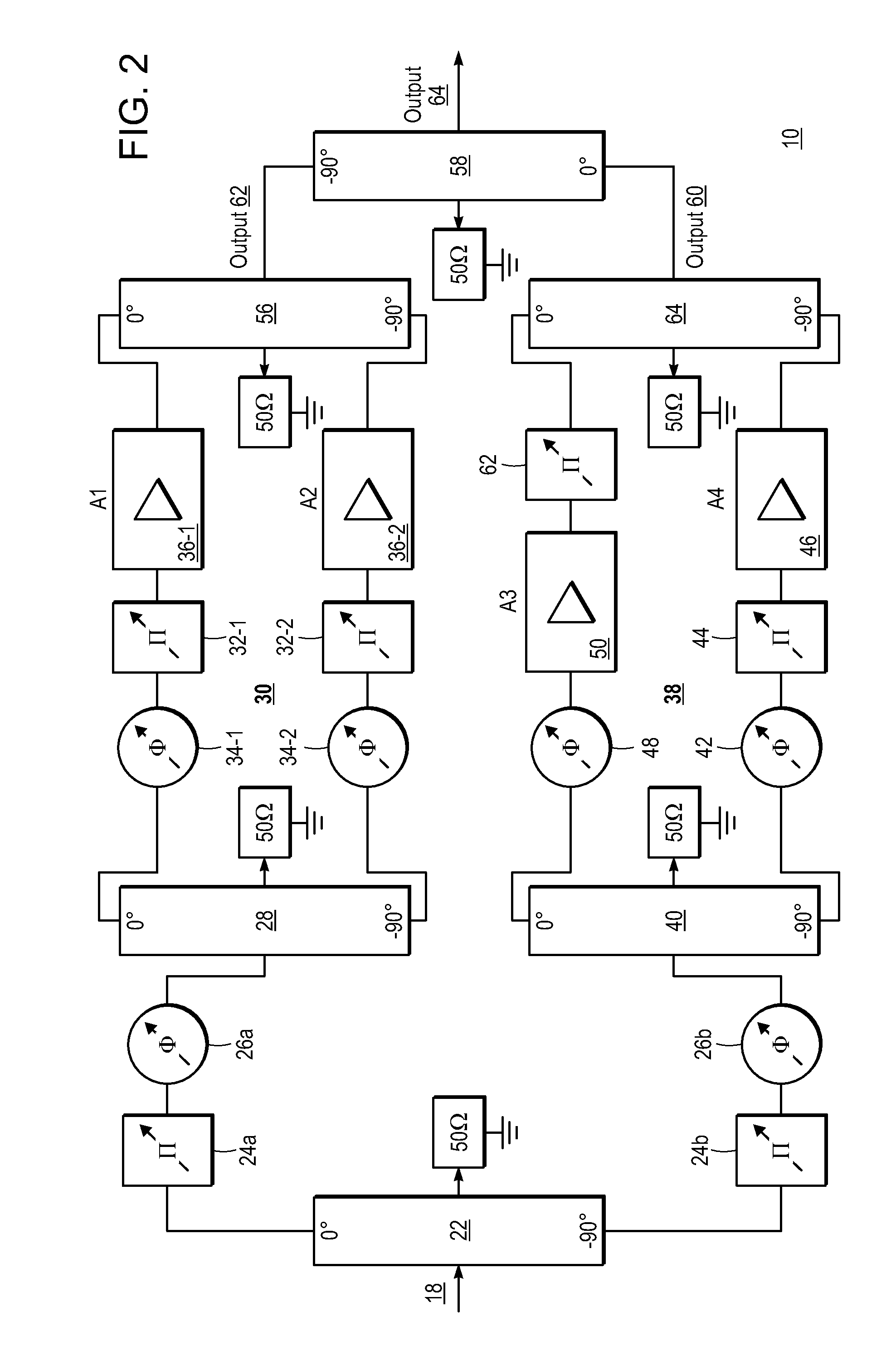
[0017]FIG. 2 is a block diagram showing an example ...


PUM


Abstract

A system including a power amplifier and a pre-distortion module coupled to the power amplifier. The pre-distortion module includes one or more smaller versions of the power amplifier to generate a pre-distortion signal that compensates for any memory-effect or inertia present in the power amplifier with application on frequency hopping and larger (up to 1 octave) instantaneous bandwidth communication systems.

Description

CROSS REFERENCE TO RELATED APPLICATION[0001]This application claims the benefit under 35 U.S.C. §119(e) of U.S. Provisional Patent Application No. 61 / 409,035, filed Nov. 1, 2010, which is hereby incorporated by reference herein in its entirety.FIELD OF THE INVENTION[0002]This invention relates generally to power amplifiers and methods for linearizing the output from these power amplifiers.BACKGROUND[0003]New communication services and the use of complex waveforms have created a demand for highly linearized power amplifiers. Deviations from linearity are manifest by spectral distortion components in the output of these amplifiers—that is, undesired energy, not contained in the original signal, inside or outside the frequency band of interest. Linearization techniques seek to reduce these distortion components, restoring signal integrity and allowing an amplifier to operate at its best spectral and power efficiency for the specific application.[0004]To date, a number of linearization ...

Claims


Application Information

Patent Timeline
Patent Type & Authority Patents(United States)
IPC IPC(8): H03F1/26
CPCH03F2200/192H03F2201/3209H03F2201/3224H03F2200/204H03F1/3282H03F2200/36H03F1/3241
Inventor CORREA, PAULOCASTRO, ANDRE A.
Owner EMPOWER RF SYST
Why Eureka
Try Eureka