Magnetic amplifier assisted LED constant current sink overhead voltage regulation

a technology of constant current sink and magnetic amplifier, applied in the direction of electric variable regulation, process and machine control, instruments, etc., can solve the problems of difficult to provide the driving function of ccfls, long operating life of leds and drawbacks, etc., to achieve the effect of maximizing efficiency

Active Publication Date: 2014-06-03
MAXIM INTEGRATED PROD INC
View PDF32 Cites 9 Cited by
  • Summary
  • Abstract
  • Description
  • Claims
  • Application Information

AI Technical Summary

Benefits of technology

[0010]Embodiments of a power circuit include a plurality of LED strings, each LED string having multiple LEDs connected in series. A plurality of magnetic amplifiers, reset current sources, and a control circuit are used to drive each LED string with equal current and to independently regulate the amount of voltage supplied to each LED to maximize efficiency. One magnetic amplifier, one reset current source, and one current sink are dedicated to each LED string. A power conversion circuit provides isolated power to the plurality of LED strings via the plurality of magnetic amplifiers. The control circuit measures the voltage drop across each LED string and determines an amount of reset control current in response to the measured voltage drop. The reset control current is supplied by the reset current source to the magnetic amplifier dedicated to the regulated LED string. The amount of reset control current supplied to the magnetic amplifier dictates the amount of voltage supplied to the LED string. The control circuit includes a separate control loop coupled to each current sink.
[0011]In one aspect, a power circuit includes a magnetic amplifier; a light emitting diode string coupled to an output of the magnetic amplifier, wherein the light emitting diode string includes a plurality of light emitting diodes coupled in series; and a control circuit coupled to the magnetic amplifier and the light emitting diode string, wherein the magnetic amplifier and the control circuit are configured to regulate a current through the LED string. In some embodiments, the power circuit also includes a current sink transistor coupled to the LED string and to the control circuit, wherein the magnetic amplifier and the control circuit are configured to maintain a compliance voltage of the current sink transistor. The control circuit includes an integrated control loop configured to regulate the current through the LED string and to control a reset current supplied to the magnetic amplifier. In some configurations, the power circuit includes a plurality of magnetic amplifiers and a plurality of light emitting diode strings, one magnetic amplifier coupled to one light emitting diode string to form a magnetic amplifier and light emitting diode string pair, wherein the control circuit includes a plurality of control loops, one control loop coupled to one magnetic amplifier and light emitting diode string pair.
[0012]In another aspect, a power circuit is disclosed that includes a power conversion module including a transformer, a primary winding of the transformer coupled to a power source; a magnetic amplifier coupled to a secondary winding of the transformer; a light emitting diode string coupled to an output of the magnetic amplifier, wherein the light emitting diode string includes a plurality of light emitting diodes coupled in series; a reset current source coupled to the output of the magnetic amplifier; a current sink coupled to an output of the light emitting diode string; and a control circuit coupled to the reset current source, the light emitting diode string, and to the current sink. In some embodiments, the power conversion module is configured for power factor correction, DC-to-DC conversion and power isolation. In some embodiment...

Problems solved by technology

As a result, providing the driving function of CCFLs is difficult.
Further, LEDs have a much longer operating life than CCFLs.
In the context of backlighting applications, LEDs also suffer from drawbacks.
A design challenge of the string based configuration is that in order to provide uniform backlighting, each of the LED strings must be driven with equal current.
However, manufactured LEDs do not have identical voltage drops, and therefore the provided anode voltage must accommodate the LED string with the highest voltage drop.
This results in increased power loss across the current sinks corresponding to those LED strings having lower voltage drops.
Although individual LEDs or even LED strings can be binned according to similar voltage drops, this comes at an added cost to the LCD panel or telev...

Method used


Image

  • Magnetic amplifier assisted LED constant current sink overhead voltage regulation
  • Magnetic amplifier assisted LED constant current sink overhead voltage regulation
  • Magnetic amplifier assisted LED constant current sink overhead voltage regulation

Examples


first embodiment

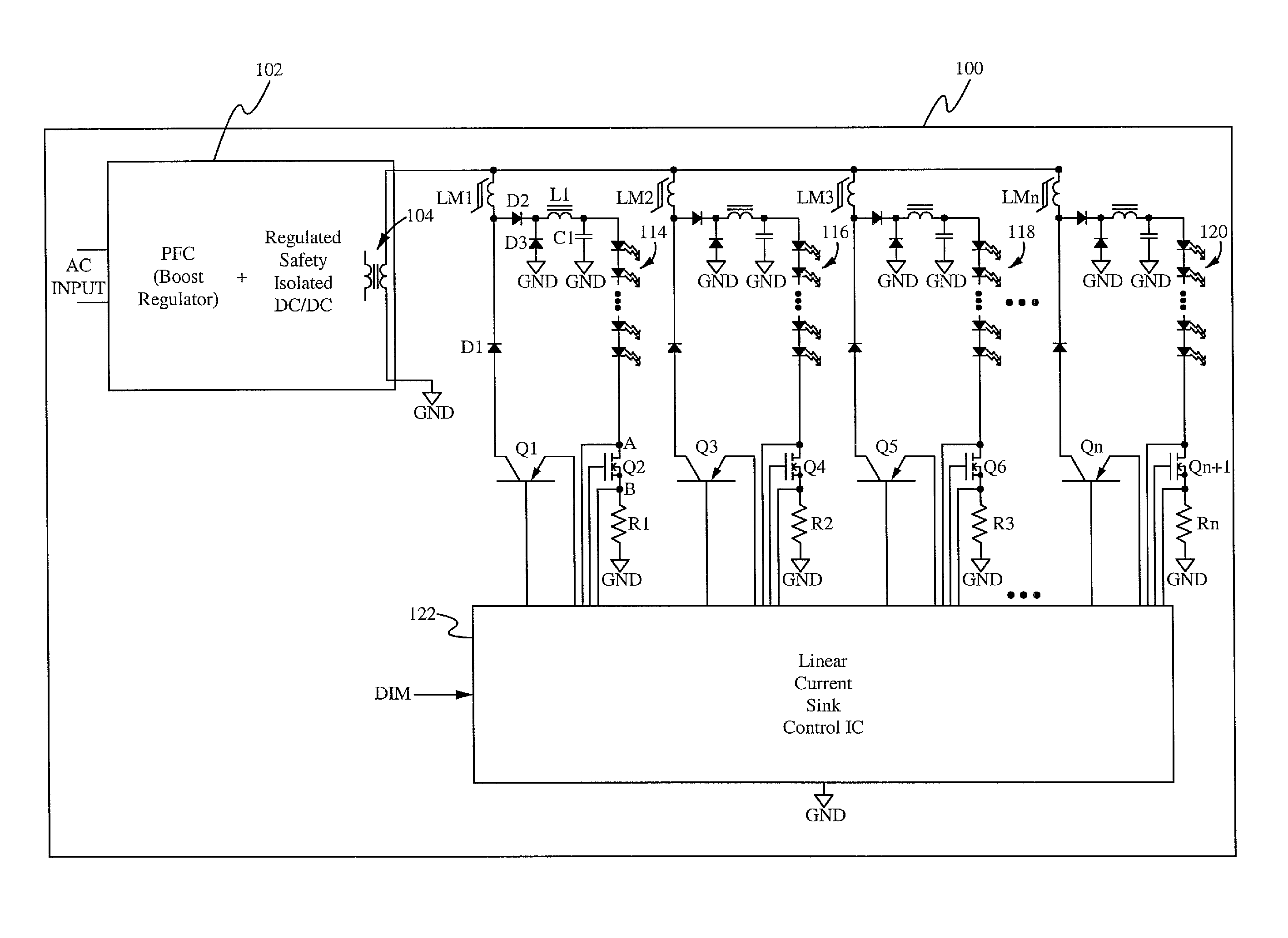
[0031]FIG. 3 illustrates a conceptual block diagram of a power circuit according to a The power circuit 100 includes a power conversion module 102, a plurality of magnetic amplifiers LM1-LMn, a plurality of LED strings 114-120, a plurality of transistors Q1-QN+1, and a linear current sink control circuit 122. For simplicity, only the circuit configuration and operation related to the LED string 114 is described below. The configuration and operation of the circuitry coupled to the remaining LED strings 116, 118, 120 are the same as that described related to the LED string 114.

[0032]One magnetic amplifier is coupled to one LED string, for example the LED string 114 is coupled to the output of the magnetic amplifier LM1. A rectifier circuit including a diode D2, a freewheeling diode D3, a filter inductor and filter L1, and a filter capacitor C1 is coupled between the magnetic amplifier LM1 and the LED string 114. In some embodiments, the diode D3 and the filter inductor and filter L1...

second embodiment

[0049]FIG. 13 illustrates a conceptual block diagram of a power circuit 200 according to a The power circuit 200 is similar to the power circuit 100 of FIG. 3 except that the reset current source and current sink for each LED string are integrated into the control circuit. Specifically, the control circuit 222 includes the functionality of the control circuit 122 as well as the reset current sources (transistors Q1, Q3, Q5, QN) and the current sinks (transistors Q2, Q4, Q6, QN+1) of the power circuit 100. In some embodiments, the control circuit 222 is a high voltage all analog circuit having no switching PWM control circuitry.

[0050]The power circuits are described above as including a current sink coupled to each LED string to regulate the current through the LED string. In some embodiments, the current through the LED string may be directly regulated by the magnetic amplifier itself, in which case the current sink transistor is only used as a dimming ON-OFF switch. One reason for...


PUM


Abstract

A power circuit include a plurality of LED strings, each LED string having multiple LEDs connected in series. A plurality of magnetic amplifiers, reset current sources, and a control circuit are used to drive each LED string with equal current and to independently regulate the amount of voltage supplied to each LED to maximize efficiency. One magnetic amplifier, one reset current source, and one current sink are dedicated to each LED string. The control circuit measures the voltage drop across each LED string and determines an amount of reset control current in response to the measured voltage drop. The reset control current is supplied by the reset current source to the magnetic amplifier dedicated to the regulated LED string. The amount of reset control current supplied to the magnetic amplifier dictates the amount of voltage supplied to the LED string.

Description

FIELD OF THE INVENTION[0001]The present invention relates to the field of power converters. More particularly, the present invention relates to the field of regulating voltage applied to LEDs using magnetic amplifiers.BACKGROUND OF THE INVENTION[0002]Light emitting diodes (LEDs) are increasingly being used for backlighting within display devices, such as liquid crystal display (LCD) televisions and monitors. Older technologies utilize CCFLs (cold cathode fluorescent lamps) for backlighting. The use of CCFLs has numerous drawbacks. For example, CCFLs contain mercury, which is a toxic material. CCFLs also require very large voltages to operate, such as between 1 kV to 5 kV. As a result, providing the driving function of CCFLs is difficult. The use of LEDs overcomes these drawbacks. LEDs do not contain mercury, and a single LED can operate at approximately 3.5 volts, which eases the system design requirements. Further, LEDs have a much longer operating life than CCFLs. The operating li...

Claims


Application Information

Patent Timeline
IPC IPC(8): H05B37/02H05B44/00
CPCH05B37/02H05B33/0827H05B45/46H05B45/3725H05B45/382H05B45/38Y02B20/30H05B45/48
Inventor NALBANT, MEHMET
Owner MAXIM INTEGRATED PROD INC
Why Eureka
Try Eureka