Plastic faucet body with copper connecting legs

a faucet body and plastic technology, applied in the direction of valve body, functional valve type, valve housing, etc., can solve the problems of high production cost of casing, easy damage of tools for machining the faucet body, and complicated machining process

Inactive Publication Date: 2014-06-10
GLOBE UNION INDAL
View PDF5 Cites 11 Cited by
  • Summary
  • Abstract
  • Description
  • Claims
  • Application Information

AI Technical Summary

Benefits of technology

[0011]The primary object of the present invention is to provide a plastic faucet body with copper connecting legs which is capable of overcoming the shortcomings of the conventional plastic faucet body with copper connecting legs.
[0027]Thereby, the lower coupling portion of the connection zone of the each support foot and the inner wall of the each copper connecting leg is moved to an upper position, such that receiving chamber is defined on the inner fence of the each copper connecting leg so as to receive the cold water pipe or the hot water pipe, and one groove is formed so as to retain the seal element and to stop the cold water from the cold water pipe or the hot water from the hot water pipe flowing into the lower coupling portion, thus avoiding water pollution. In addition, the each copper connecting leg can be also fitted with the each support foot, after the seal element is retained in each groove so as to stop water, which flows into the lower coupling portion, leaking outwardly.

Problems solved by technology

But the machining process is complicated and takes a long time.
Likewise, the tools for machining the faucet body are damaged easily, and the faucet body is casting molded from copper material, thereby casing high production cost.
However, a slit generates on a connection zone of the copper leg and the support foot, thus leaking water and having water pollution.

Method used


Image

  • Plastic faucet body with copper connecting legs
  • Plastic faucet body with copper connecting legs
  • Plastic faucet body with copper connecting legs

Examples


Embodiment Construction

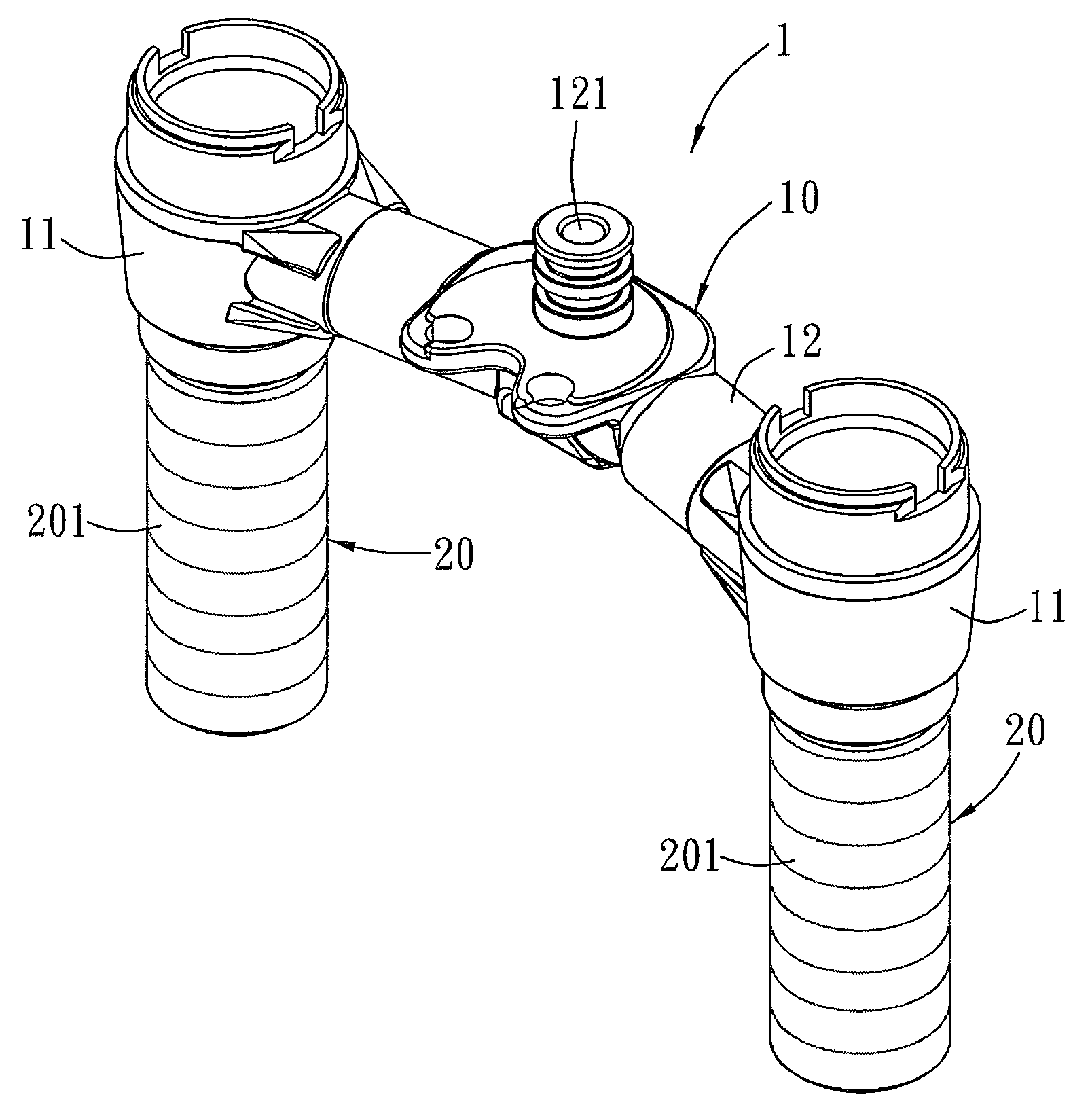
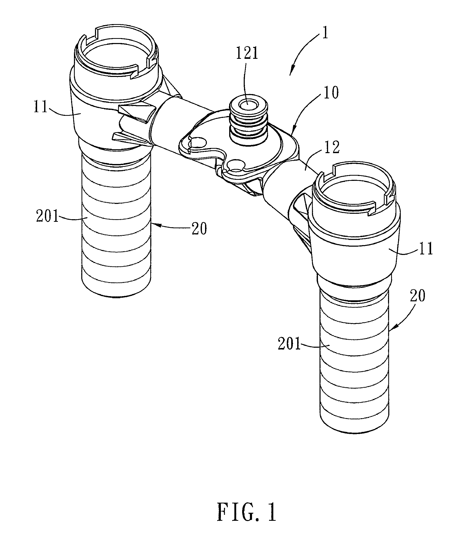
[0042]FIGS. 1-4 show a plastic faucet body with copper connecting legs according to a first embodiment of the present invention. A faucet body 1 comprises a plastic member 10 and two copper connecting legs 20.

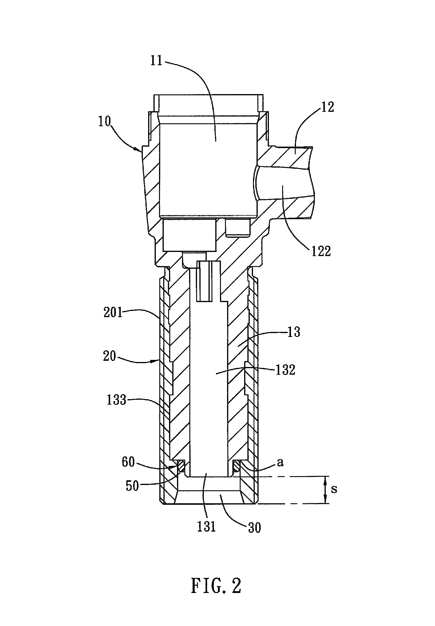
[0043]The plastic member 10 is injection molded from plastic material and includes two seat portions 11 mounted on two sides thereof, a connecting portion 12 defined between the two seat portions 11, and two support feet 13 extending downwardly from two bottom ends of the two seat portions 11. As shown in FIG. 4, each support foot 13 has an inlet 131 formed on a bottom end thereof and has a channel 132 arranged in the each support foot 13 and communicating with each seat portion 11. The connecting portion 12 has at least one exit 121 defined on a middle section thereof and has a tunnel 122 defined therein and communicating with the each seat portion 11.

[0044]The two copper connecting legs 20 are made of cooper material, and each copper connecting leg 20 is engaged on an outer w...


PUM


Abstract

A plastic faucet body with copper connecting legs contains a plastic member including two seat portions, a connecting portion having at least one exit and a tunnel, and two support feet, each having an inlet and a channel; two copper connecting legs engaged on the two support feet. A bottom end portion of each copper connecting leg beyond a bottom end of the each support foot forms a distance so that between the each copper connecting leg and the each support foot is defined a receiving chamber. A lower coupling portion forms on a connection zone of the each support foot and the each copper connecting leg. A groove communicates with the receiving chamber and the lower coupling portion. A seal element is retained with the groove to stop cold water from the cold water pipe or hot water from the hot water pipe flowing into the lower coupling portion.

Description

[0001]This application is a Continuation-in-Part of application Ser. No. 13 / 714,533, filed Dec. 14, 2012.BACKGROUND OF THE INVENTION[0002]1. Field of the Invention[0003]The present invention relates to a plastic faucet body with copper connecting legs.[0004]2. Description of the Prior Art[0005]Conventional faucet comprises a faucet body, and more particularly to a H-shaped faucet body with two inlets. This H-shaped faucet body comprises two seat portions mounted on two sides thereof, a connecting portion defined between the two seat portions, and two support feet extending downwardly from two bottom ends of the two seat portions. Each support foot has an inlet formed on a bottom end thereof for flowing cold water or hot water and has a channel for communicating with each seat portion. The each seat portion is used to receive a valve member controlled by a handle. The connecting portion has at least one outlet defined on a middle section thereof so as to connect with a water pipe or ...

Claims


Application Information

Patent Timeline
Patent Type & Authority Patents(United States)
IPC IPC(8): F16K27/06F16K5/00E03C1/04
CPCE03C1/0403E03C1/0401Y10T137/6157Y10T137/9464Y10T137/6014Y10T137/598
Inventor YANG, CHAOTAYUAN, CHIAHUALIN, YIPINGHU, SHENGPING
Owner GLOBE UNION INDAL
Why Eureka
Try Eureka