Element removal design in microwave filters

Active Publication Date: 2014-06-10
MURATA MFG CO LTD
View PDF17 Cites 74 Cited by
  • Summary
  • Abstract
  • Description
  • Claims
  • Application Information

AI Technical Summary

Problems solved by technology

In particular, such electrical filters are used to select desired electrical signal frequencies from an input signal by passing the desired signal frequencies, while blocking or attenuating other undesirable electrical signal frequencies.
This requirement for low resistance tends to drive the siz

Method used


Image

  • Element removal design in microwave filters
  • Element removal design in microwave filters
  • Element removal design in microwave filters

Examples


Embodiment Construction

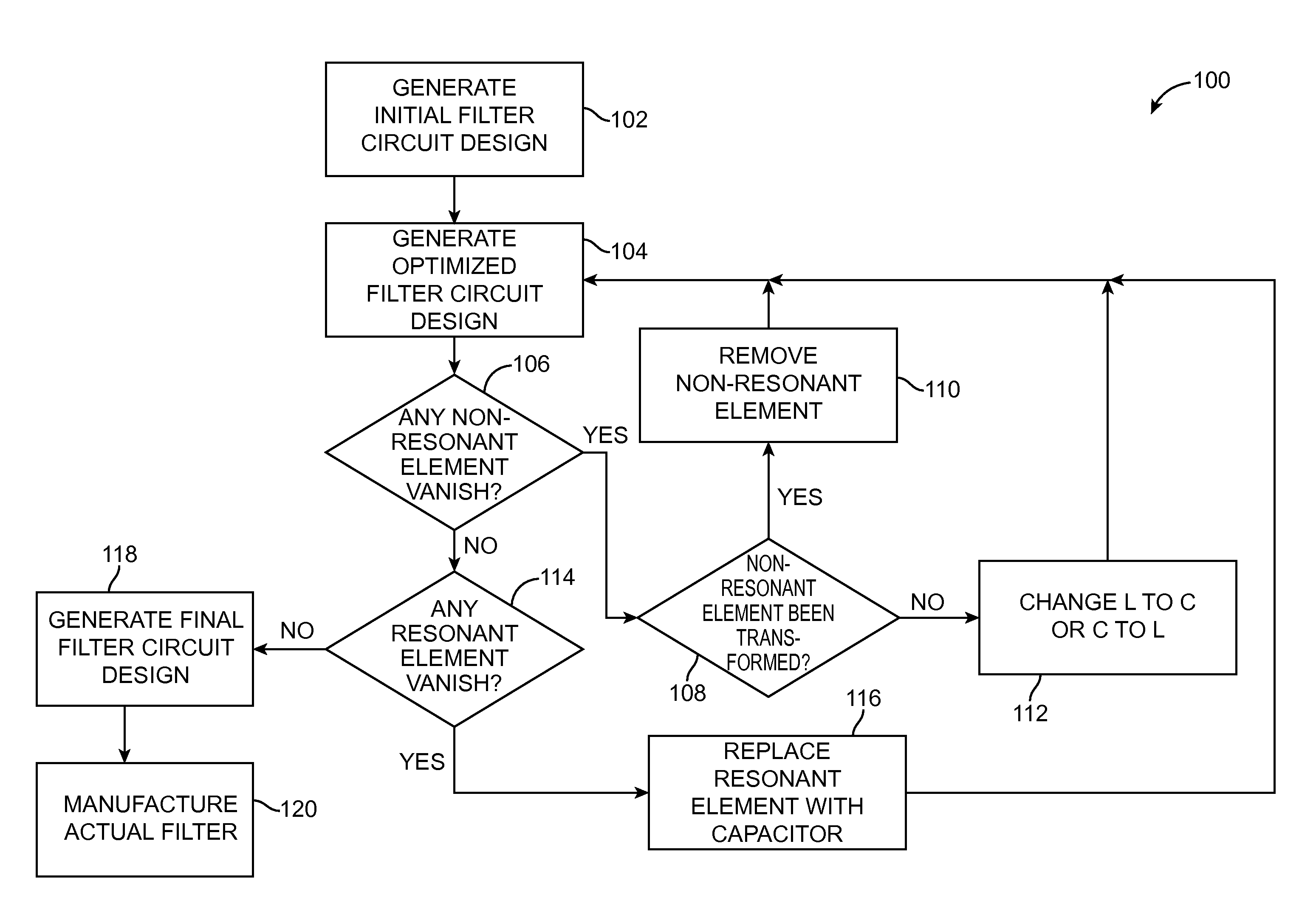
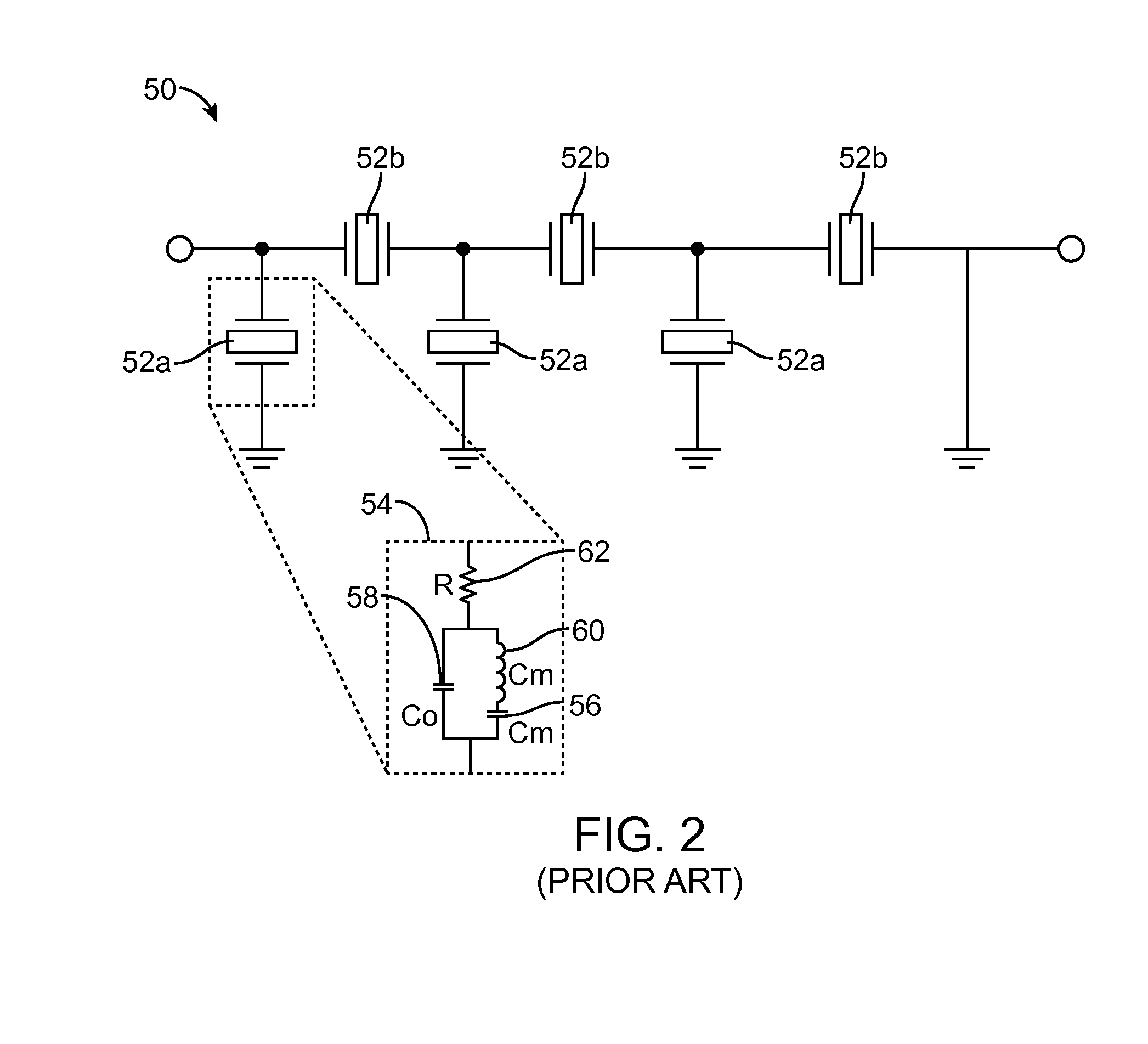
[0038]The microwave filter design optimization technique optimizes an acoustic wave (AW) microwave filter (such as surface acoustic wave (SAW), bulk acoustic wave (BAW), and film bulk acoustic wave (FBAR) filters), by changing the circuit element values, changing the circuit element type, and / or discretely removing extra or unnecessary circuit elements. These elements may include inductors, capacitors, and acoustic resonators (modeled, e.g., using the modified Butterworth-Van Dyke (MBVD) model).

[0039]This optimization technique utilizes several traditional computer optimization methods to enable the improved optimization of more complex circuits in the initial design than may be possible in the prior art. These initial filter circuit designs may be produced using any design method, for instance image design or network synthesis. This optimization technique results in a final filter circuit design with a reduced number elements compared to the initial filter circuit design, while sim...


PUM


Abstract

A method of designing a microwave filter using a computerized filter optimizer, comprises generating a filter circuit design in process (DIP) comprising a plurality of circuit elements having a plurality of resonant elements and one or more non-resonant elements, optimizing the DIP by inputting the DIP into the computerized filter optimizer, determining that one of the plurality of circuit elements in the DIP is insignificant, removing the one insignificant circuit element from the DIP, deriving a final filter circuit design from the DIP, and manufacturing the microwave filter based on the final filter circuit design.

Description

RELATED APPLICATION DATA[0001]The present application claims the benefit under 35 U.S.C. §119 to U.S. provisional patent application Ser. No. 61 / 802,114, filed Mar. 15, 2013. The foregoing application is hereby incorporated by reference into the present application in its entirety.FIELD OF THE INVENTION[0002]The present inventions generally relate to microwave filters, and more particularly, to acoustic wave microwave filters designed for narrow-band applications.BACKGROUND OF THE INVENTION[0003]Electrical filters have long been used in the processing of electrical signals. In particular, such electrical filters are used to select desired electrical signal frequencies from an input signal by passing the desired signal frequencies, while blocking or attenuating other undesirable electrical signal frequencies. Filters may be classified in some general categories that include low-pass filters, high-pass filters, band-pass filters, and band-stop filters, indicative of the type of freque...

Claims


Application Information

Patent Timeline
IPC IPC(8): G06F17/50H03F3/45G06G7/48H03K3/45G06G7/50H03H7/00
CPCG06F17/5072G06F17/5063G06F17/5045H03H9/46G06F30/373G06F30/00G06F30/36G06F30/30G06F30/392H03H7/00G06G7/48H03F3/45G06G7/50G06F30/367G06F30/398H03H9/542
Inventor FENZI, NEALRAIHN, KURT
Owner MURATA MFG CO LTD
Why Eureka
Try Eureka