Aircraft fuel tank ventilation

a technology for aircraft and fuel tanks, applied in the direction of isotope separation, applications, lighting and heating apparatus, etc., can solve the problems of affecting the reliability of fuel system components, affecting the operation delay, and water is an unavoidable contaminant in fuel, so as to prevent ice accumulation, prevent ice accumulation, and promote drying

Active Publication Date: 2014-06-17
AIRBUS OPERATIONS LTD
View PDF8 Cites 5 Cited by
  • Summary
  • Abstract
  • Description
  • Claims
  • Application Information

AI Technical Summary

Benefits of technology

[0012]The invention is advantageous in that water can be effectively removed from air entering the aircraft fuel tank. In this way, the content of water in the fuel tank can be kept low, which improves fuel system component reliability, reduces maintenance activities, and reduces microbiological contamination.
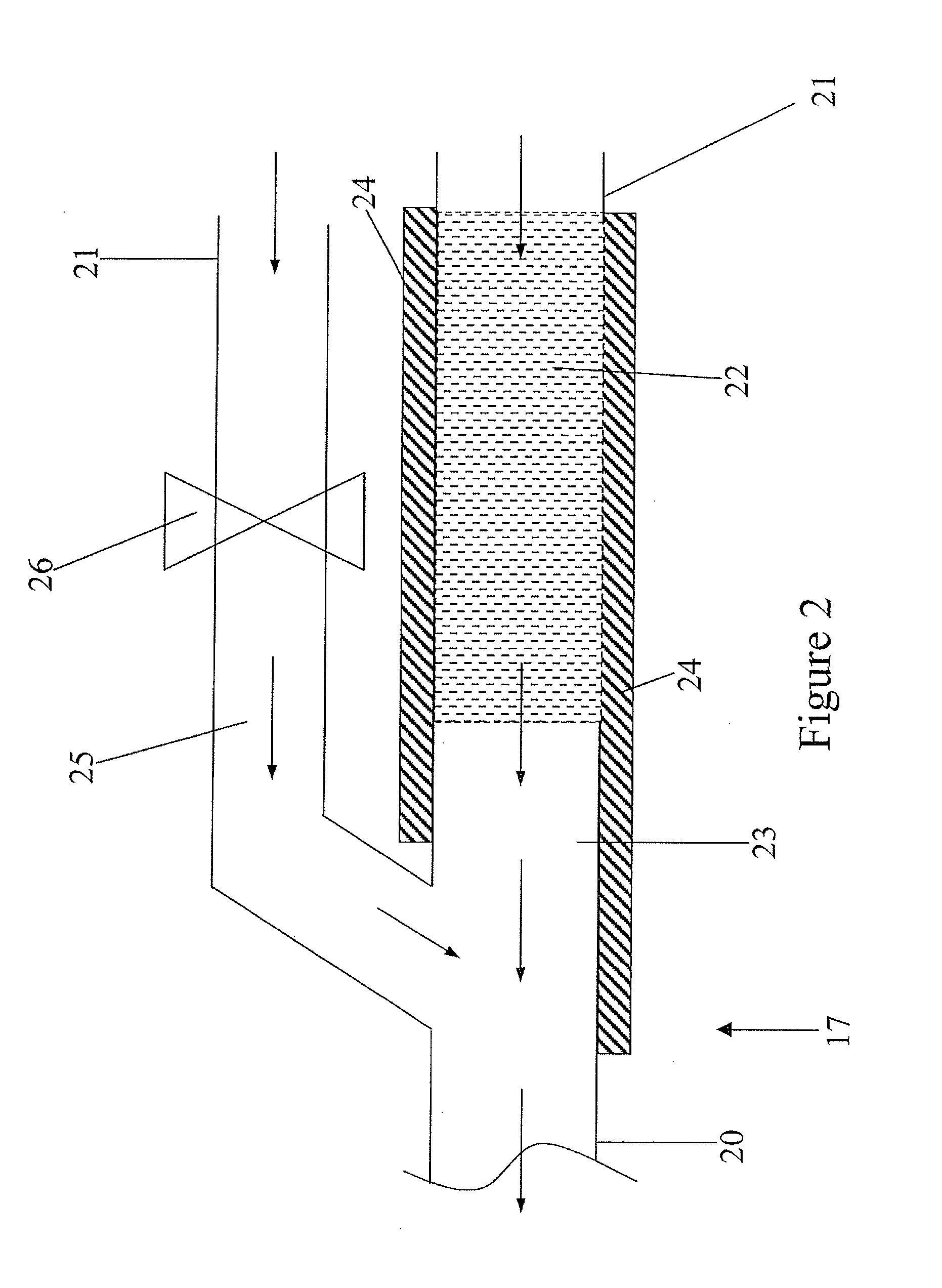
[0014]The dehumidifying device may include a heating element. The heating element may be a heat exchanger or an electrical heating device, for example, for heating the desiccant medium and / or for preventing ice accumulation within the device. Alternatively, or additionally, the dehumidifying device may further comprise a hot air outlet disposed adjacent the desiccant medium. Heating the desiccant medium promotes drying by evaporating moisture into air passing through the desiccant medium in a flow direction towards the atmosphere, so regenerating the desiccant medium. Heating the dehumidifying device as a whole prevents ice accumulation and therefore promotes free flow of air through the conduits of the device.

Problems solved by technology

Water is an unavoidable contaminant in fuel.
It can affect fuel system component reliability and lead to operational delays and increased maintenance activities.
This results a net outflow of air through the ventilation system.
This results a net inflow of ambient air through the ventilation system.
The fuel system is cold during descent as the aircraft will likely have just spent some time at cold, cruise temperatures.

Method used


Image

  • Aircraft fuel tank ventilation
  • Aircraft fuel tank ventilation
  • Aircraft fuel tank ventilation

Examples


Embodiment Construction

)

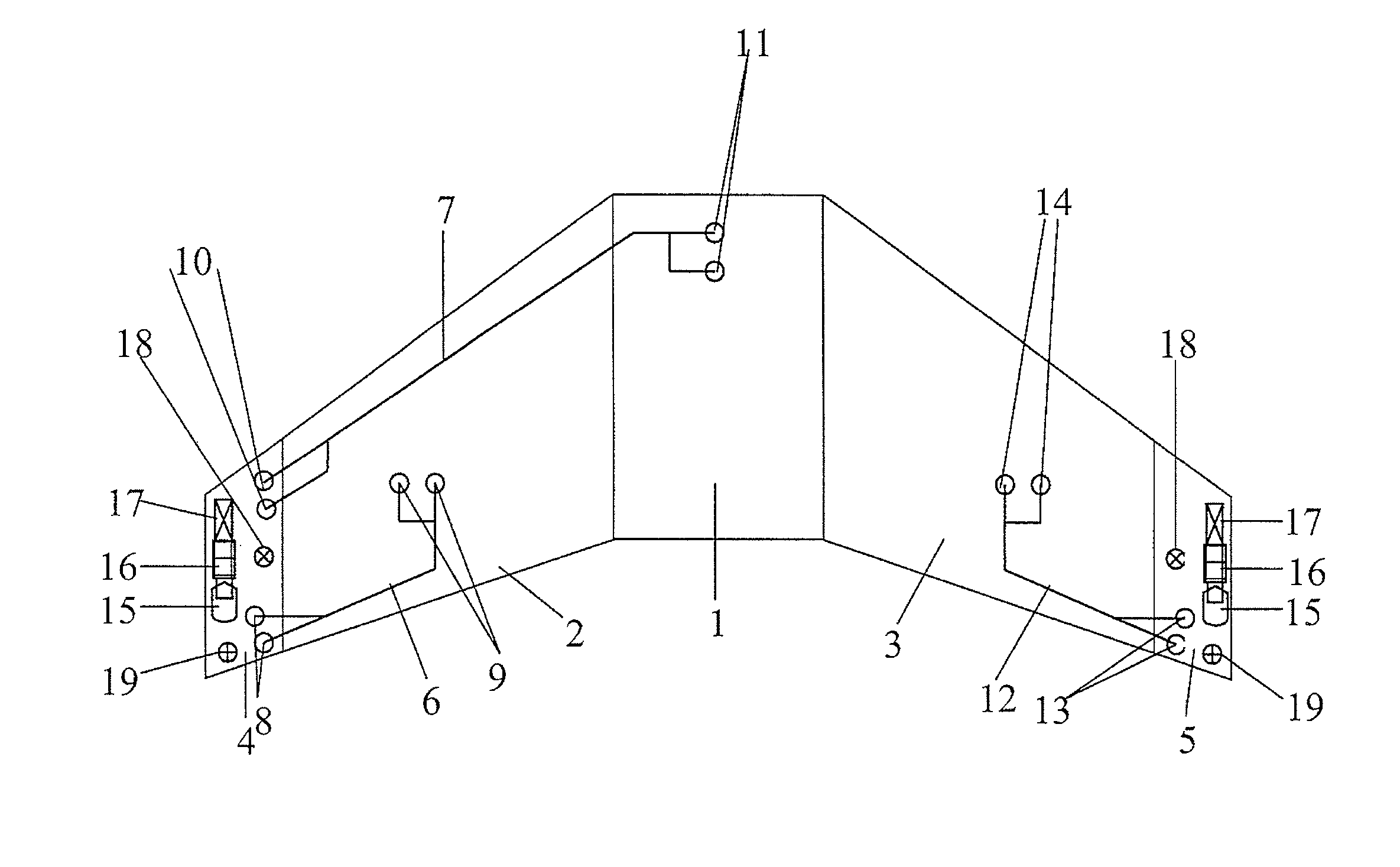
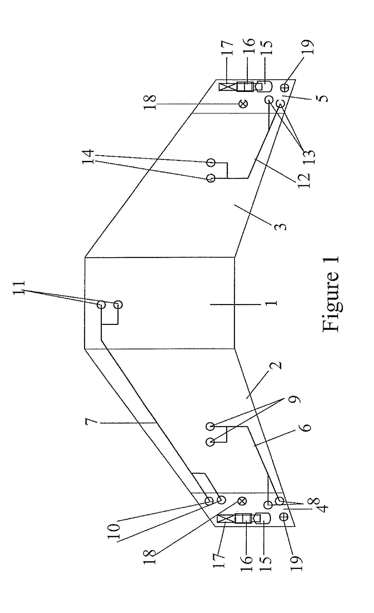
[0028]FIG. 1 shows a general ventilation system architecture for a three-tank configuration of an aircraft fuel system. The fuel system includes a centre tank 1, a left wing tank 2 and a right wing tank 3. The ventilation system includes a left vent tank 4 and a right vent tank 5. The left vent tank 4 ventilates the centre tank 1 and the left wing tank 2 by means of ventilation pipes 6, 7 which open into ventilation inlets 8, 9, 10, 11. The right vent tank 5 ventilates the right wing tank 3 by means of ventilation pipe 12 which opens into ventilation inlets 13 and 14. The centre tank could equally be vented by the right vent tank. It is to be noted that all of the fuel tanks are ventilated but are not cross-ventilated, i.e. the left and right vent tanks are not connected by ventilation paths.

[0029]Each vent tank 4, 5 includes a NACA vent, or NACA scoop, 15 which opens to the atmosphere on the lower aerodynamic surface of the aircraft wing. The vent tanks 4, 5 further include a vent...


PUM


Abstract

An aircraft fuel tank ventilation system includes a dehumidifying device disposed in flow communication between a vent open to the atmosphere and a fuel tank. A method of dehumidifying air introduced into an aircraft fuel tank via a ventilation system includes directing atmospheric air through a dehumidifying device disposed in flow communication between a vent of the ventilation system and the fuel tank, which removes water vapor from the air flowing from the vent towards the fuel tank. A method of regenerating a desiccant medium used to dehumidify air introduced into an aircraft fuel tank via a ventilation system includes directing air through the desiccant medium so as to dry the desiccant medium.

Description

RELATED APPLICATIONS[0001]The present application is a National Phase of International Application Number PCT / GB2010 / 051131, filed Jul. 9, 2010 and claims priority from British Application Number 0912710.1, filed Jul. 22, 2009.FIELD OF THE INVENTION[0002]The present invention relates to an aircraft fuel tank ventilation system having a dehumidifying device. The present invention also relates to a method of dehumidifying air being introduced into an aircraft fuel tank, and to a method of regenerating a desiccant medium used to dehumidify air introduced into an aircraft fuel tank.BACKGROUND OF THE INVENTION[0003]Water is an unavoidable contaminant in fuel. It can affect fuel system component reliability and lead to operational delays and increased maintenance activities. In addition, the propensity for microbiological contamination is directly proportional to the presence of water and the temperature within fuel tanks. Sources of water in aircraft fuel tanks is from fuel loaded into t...

Claims


Application Information

Patent Timeline
Patent Type & Authority Patents(United States)
IPC IPC(8): B01D53/02
CPCB64D37/34B64D37/10B64D37/32Y10T137/86324
Inventor LAM, JOSEPH K-WPARMENTER, DAVIDMASTERS, SIMON
Owner AIRBUS OPERATIONS LTD
Why Eureka
Try Eureka