
Sheathed Element Glow Plug Having an Integrated Pressure Measuring Element

a technology of pressure measuring element and glow plug, which is applied in the direction of lighting and heating apparatus, instruments, machines/engines, etc., can solve the problems of increasing assembly effort, affecting the accuracy of the output, so as to reduce production costs, avoid delivery bottlenecks, and improve the effect of accuracy

Inactive Publication Date: 2010-02-11
ROBERT BOSCH GMBH
View PDF1 Cites 12 Cited by
  • Summary
  • Abstract
  • Description
  • Claims
  • Application Information

AI Technical Summary

Benefits of technology

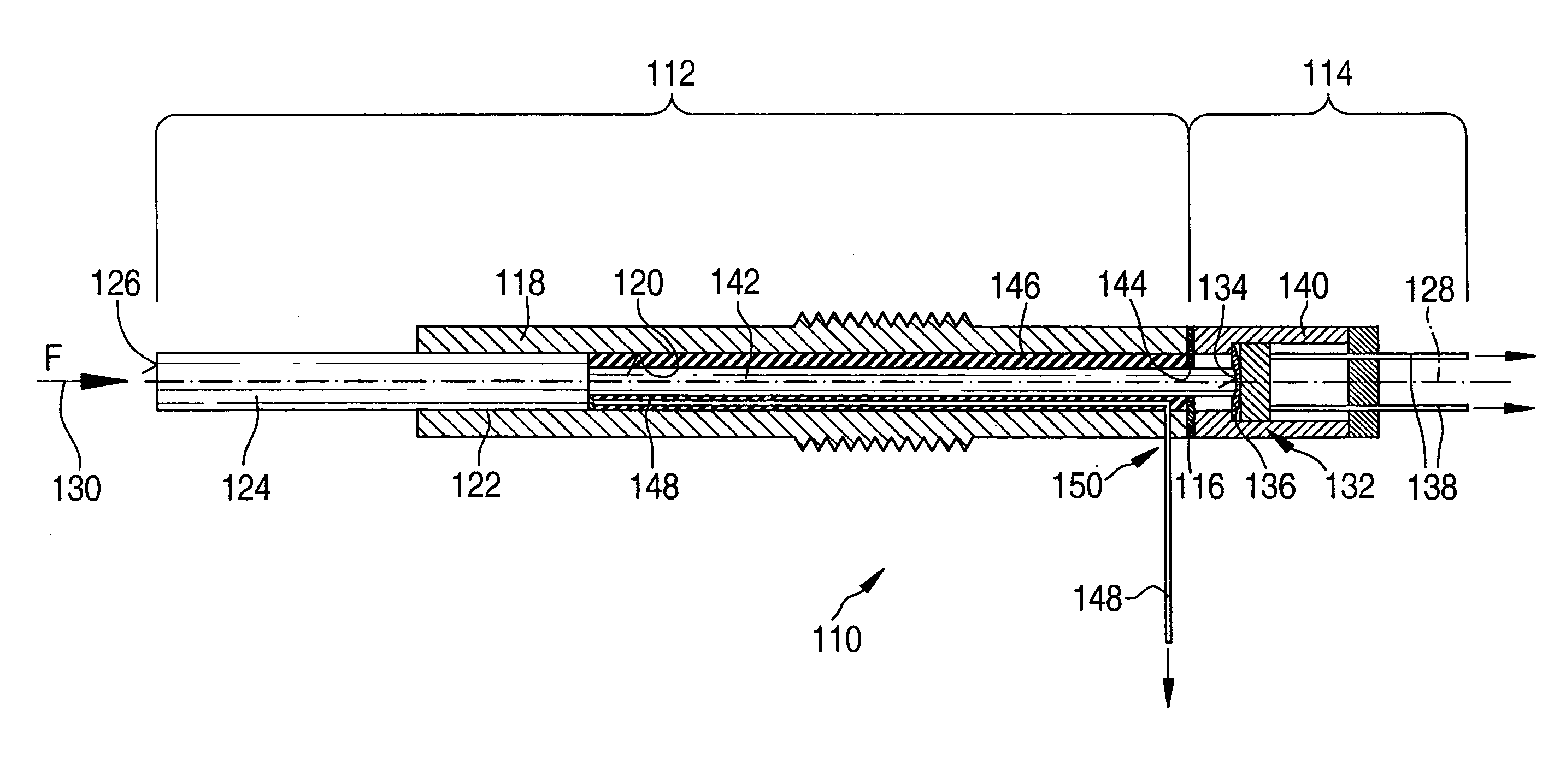
[0014]An example sheathed element glow plug according to the present invention has numerous advantages compared to conventional devices. In particular, the use of a separate pressure measuring module and the modular design have the effect that the external dimensions of the at least one force measuring element are no longer limited by the internal space of the glow plug housing. This makes a greater selection of force measuring elements commercially available, which helps reduce production costs and avoid delivery bottlenecks. Occasionally force measuring elements having a higher accuracy, lower temperature dependence, and other advantageous properties may also be used, which, however, were not integratable into conventional sheathed element glow plugs due to the reduced space available for installation.
[0015]Furthermore, the modular design of the sheathed element glow plug has the effect that a high degree of customer-independence is ensured in manufacturing and assembly, so that, for example, the same type of sheathed element glow plug may be integrated into different engine types. For example, simple replacement of the pressure measuring module is sufficient for this purpose.
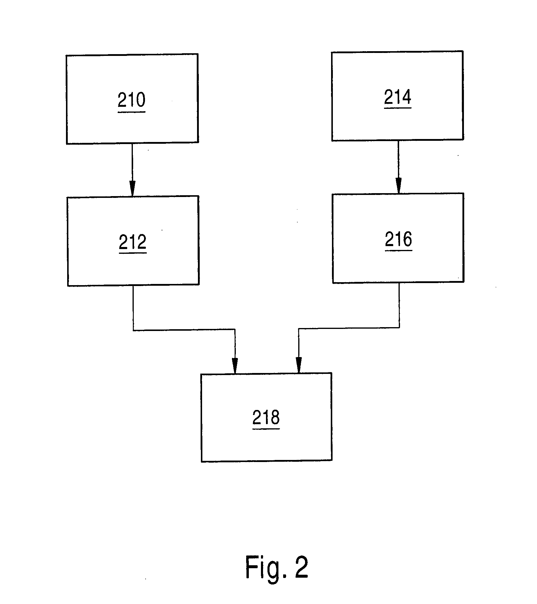
[0017]In this way errors may be detected and eliminated early in the manufacturing process, which considerably reduces rejects, lowers costs, and increases the reliability of the components. Subsequently the pressure measuring module and the first module are connected to each other in such a way that a force is transmittable to the at least one force measuring element via the heating element. This connection may be achieved via an integral joint, for example, welding, and / or a friction-locked joint.
[0019]This additional at least one force transmission element offers the advantage in particular that the heating element and the at least one force measuring element may be spatially separated. The pressure measuring module may thus be situated outside the combustion chamber of the internal combustion engine, so that the at least one force measuring element is exposed to the least possible thermal stresses and temperature fluctuations. Since the signal characteristic of many commercially available force measuring elements significantly depends on the operating temperature and / or temperature fluctuations, this design according to the present invention is highly advantageous for the signal quality.
[0021]In the design in which at least one force transmission element is used, it has been found advantageous if the sheathed element glow plug also has a vibration damping element. This vibration damping element may fill, completely or partially, in particular at least one cavity between the at least one force transmission element and the glow plug housing. In particular, if elongated force transmission elements are used, for example, a force transmission ram, this has been found advantageous for reducing the vibrations of the at least one force transmission element in order to avoid undesirable vibrations and thus undesirable components in the electrical signal of the at least one force measuring element.

Problems solved by technology

However, for using such devices, a separate bore hole must be provided in the cylinder head wall, which means additional assembly effort.
In addition, stand-alone sensors require additional bore holes in the cylinder head of the internal combustion engine, which, in particular in the case of four-valve engines as designed today, raises considerable problems due to the very scarce available space.
Furthermore, in general, systems of this type are relatively expensive and the service life of systems of this type is significantly shorter than that of a typical vehicle, mostly due to the high operating temperatures.
On the other hand, the signal quality of such combustion chamber pressure sensors is strongly dependent on the variation of forces in the entire mechanical complex and usually does not meet the requirements that have been set.
DE 196 80 912 C2 has the disadvantage in particular that the pressure sensor is directly connected to the heating section and is therefore exposed to high thermal stresses and temperature fluctuations.
DE 196 80 912 C2 is complicated because the heating section must first be introduced into the body of the glow plug, whereafter the pressure sensor must be subsequently centrally positioned on the heating section to ensure faultless functionality of the device.
Subsequently, the pressure sensor must be fastened to the side of the device facing away from the cylinder using the fastening device, which in turn carries the risk of a displacement of the pressure sensor.
Testing the functionality of the pressure sensor is not possible until the glow plug is completely assembled.
DE 102 18 544 has, however, the disadvantage of a large number of parts.
Furthermore, the connection between the core and the pressure sensor situated concentrically around this core may present difficulties in the assembly because stresses may occur between the core and the pressure sensor.
Occasionally force measuring elements having a higher accuracy, lower temperature dependence, and other advantageous properties may also be used, which, however, were not integratable into conventional sheathed element glow plugs due to the reduced space available for installation.

Method used


Image

  • Sheathed Element Glow Plug Having an Integrated Pressure Measuring Element
  • Sheathed Element Glow Plug Having an Integrated Pressure Measuring Element
  • Sheathed Element Glow Plug Having an Integrated Pressure Measuring Element

Examples


Embodiment Construction

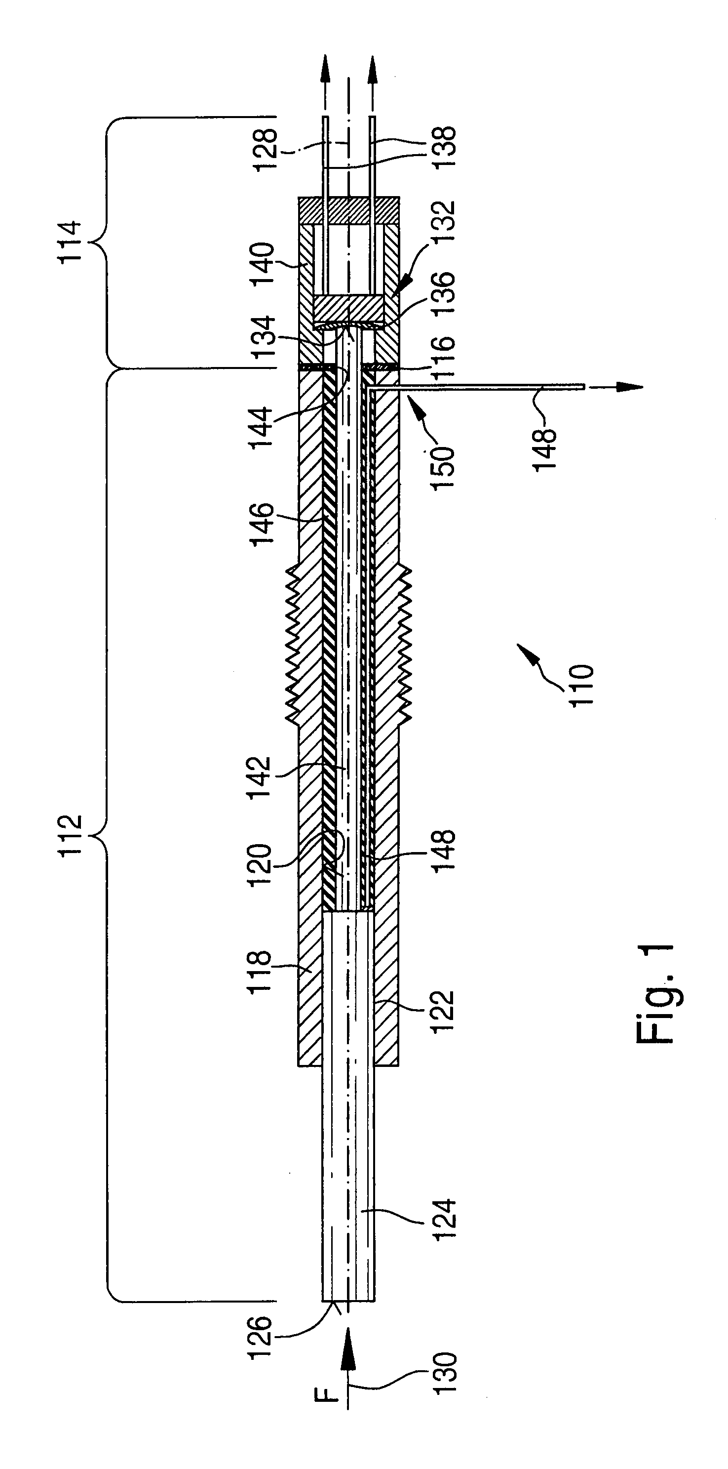
[0026]FIG. 1 shows a specific embodiment of a sheathed element glow plug 110 according to the present invention. Sheathed element glow plug 110 has a first module 112 (glow plug module) and a pressure measuring module 114. Both modules are separated along an interface by a separating wall 116, which may be a component of pressure measuring module 114 or also of glow plug module 112. Two separating walls 116 are also possible, one separating wall being a component of glow plug module 112 and one separating wall being a component of pressure measuring module 114. Pressure measuring module 114 and glow plug module112 may be connected by welding, for example. A threaded connection using an appropriate union nut is also conceivable.

[0027]Glow plug module 112 has a housing 118 having an essentially cylindrical interior space 120. At one end of housing 118 facing away from pressure measuring module 114 and facing a combustion chamber of the internal combustion engine, housing 118 has a sea...


PUM

PropertyMeasurementUnit
Forceaaaaaaaaaa
Piezoelectricityaaaaaaaaaa

Abstract

In combustion chamber signal-based engine control in particular, a reliable and at the same time cost-effective option for detecting a combustion chamber pressure in compression-ignition internal combustion engines is required. A sheathed element glow plug is proposed, which has a glow plug module and a pressure measuring module connected to the glow plug module. The glow plug module has a heating element and a glow plug housing. The pressure measuring module has at least one force measuring element, which is integrated into the pressure measuring module. The at least one force measuring element is designed to generate an electrical signal as a function of a force. In the mounted state of the sheathed element glow plug, the at least one force measuring element is connected to the heating element in such a way that a force is transmittable to the at least one force measuring element via the heating element.

Description

FIELD OF THE INVENTION[0001]The present invention relates to a sheathed element glow plug having an integrated pressure measuring element and a method for manufacturing a sheathed element glow plug of this type. In particular, the present invention relates to a sheathed element glow plug which, in addition to a heating element and a glow plug housing, has a pressure measuring module having at least one force measuring element.BACKGROUND INFORMATION[0002]As a result of increasingly strict legal exhaust gas regulations, in particular for diesel engines, the requirements for reduced emissions of harmful substances by compression-ignition internal combustion engines are becoming stricter. Modern engine management systems should ensure low fuel consumption, while having a long service life.[0003]Combustion in the combustion chamber of a diesel engine may be optimized in particular by using regulated injection of fuel. This regulated injection may be controlled in particular by electronic...

Claims


Application Information

Patent Timeline
IPC IPC(8): F23Q7/22
CPCF02P19/028F23Q7/001Y10T29/49083G01L23/10F23Q2007/002
Inventor KERN, CHRISTOPHSCHOTT, STEFFENSALTIKOV, PAVLO
Owner ROBERT BOSCH GMBH
Learn More