
Anti-jam apparatus for baseband radar systems

a radar system and anti-jam technology, applied in communication jamming, instruments, measurement devices, etc., can solve the problems of reducing the effectiveness of weapons, insensitive to multiple target deception and broadband noise jammers, and vulnerable to electronic countermeasures (ecm) such as cw or narrow band jammers

Active Publication Date: 2014-06-17
UNISYS CORP
View PDF12 Cites 1 Cited by
  • Summary
  • Abstract
  • Description
  • Claims
  • Application Information

AI Technical Summary

Benefits of technology

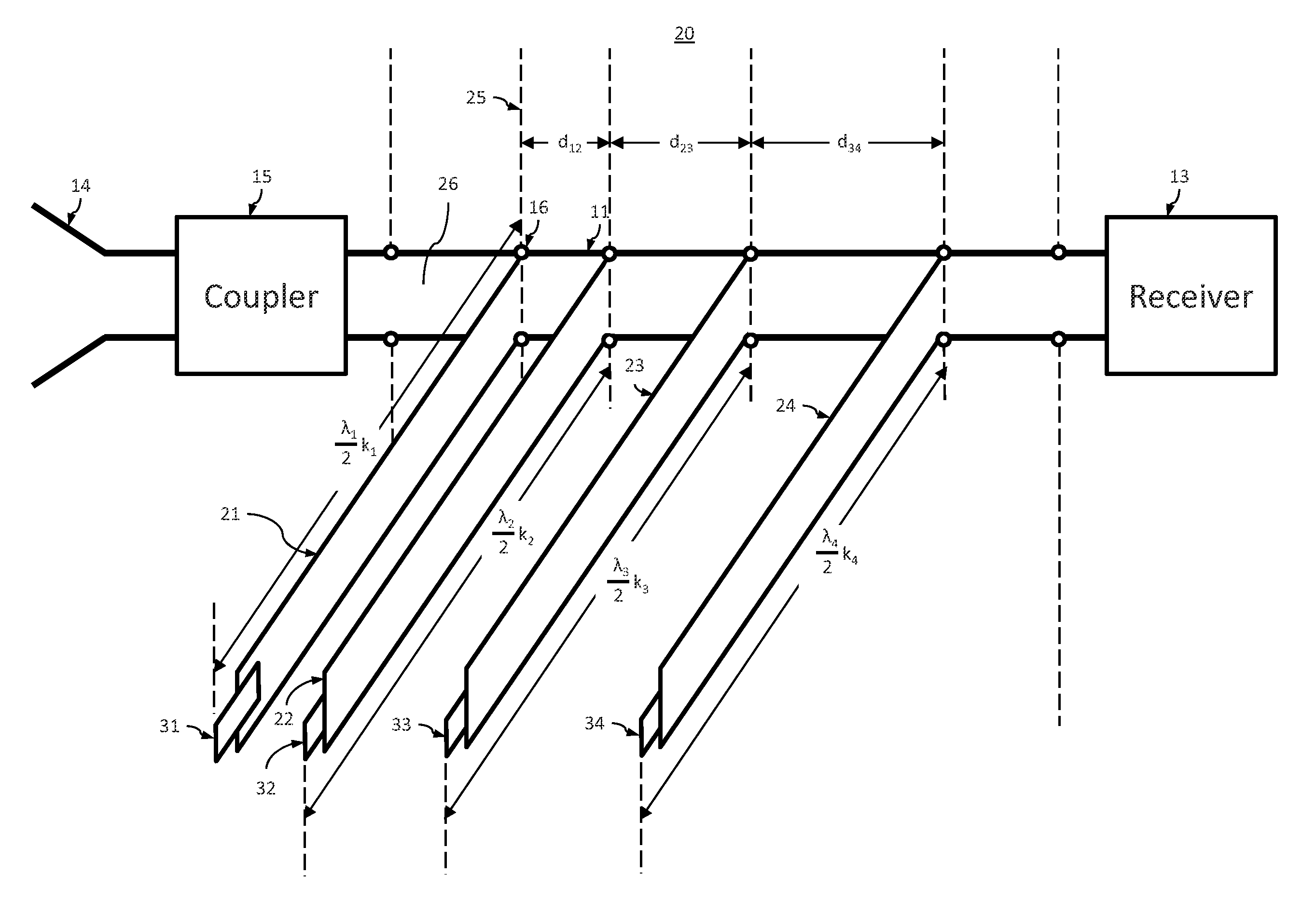
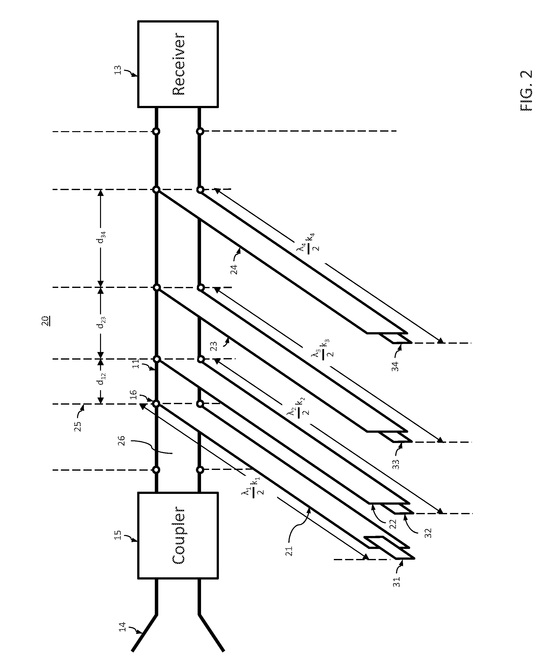
The present invention relates to an anti-jam device for a baseband radar system. The device includes a main transmission line and multiple short-circuited stub transmission lines that are positioned in parallel relation to the main line. The stub lines create a desired frequency stop band in the steady state operating condition, which filters out CW signals and partially filters out baseband pulses while still allowing them to propagate along the main line. This results in reduced interference and improved radar system performance.

Problems solved by technology

These devices, however, though insensitive to multiple target deception and broadband noise jammers because of receiver range gates that are only a few nanoseconds wide, are vulnerable to electronic countermeasures (ECM) such as CW or narrow band jammers operating at frequencies which are of the order of the reciprocal of the substantially baseband pulse.
If a baseband radar system were employed as a terminal altitude sensing device for a free falling bomb, a CW jamming signal could cause the bomb to prematurely explode thus reducing the effectiveness of the weapon.
Providing a narrow range gate to reduce the probability of false alarms with each cycle of CW signal concomitantly requires a moving range gate to cover the desired over-all range, thus adding an undesired complexity.

Method used


Image

  • Anti-jam apparatus for baseband radar systems
  • Anti-jam apparatus for baseband radar systems
  • Anti-jam apparatus for baseband radar systems

Examples


Embodiment Construction

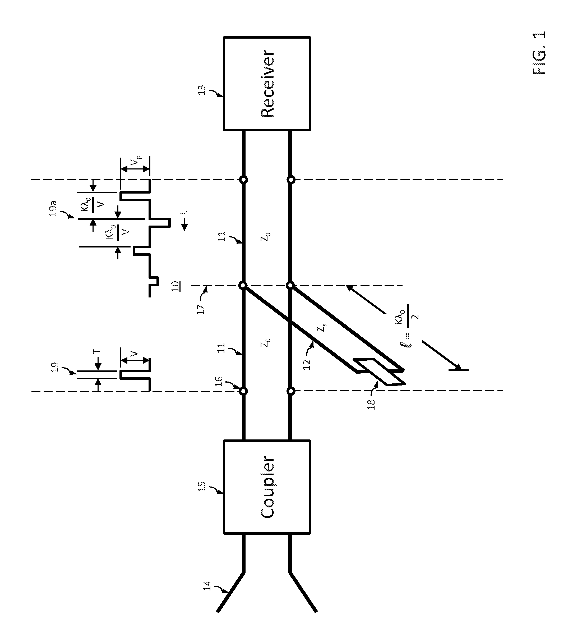
[0008]All networks provide transient and steady state responses to applied signals, which together constitute the total response thereto. When a CW signal is initially applied to a quiescent linear, time invariant network, the change from no signal to signal elicits a transient response. This transient response decays to substantial extinction after a time lapse determined by the network parameters, from the initial signal application and the network steady state response is obtained thereafter. A substantially baseband pulse, with a duration in the order of a nanosecond exhibits such a rapid change of state that when it is applied to a network only the transient response is elicited.

[0009]Refer now to FIG. 1, wherein an anti-jam filter 10 it comprising a main transmission line 11, having characteristic impedance zo, and a stub transmission line 12, having characteristic impedance zs, is shown coupled between a baseband receiver 13 and a baseband receiving antenna 14 which may be di...


PUM


Abstract

A filter which highly attenuates CW signals within specified frequency bands while allowing baseband pulses to pass therethrough with relatively low attenuation is provided. The filter comprises a main transmission line and stub transmission lines that are coupled in parallel relationship with the main transmission line. Each of the stub transmission lines is terminated with a short circuit or other appropriate impedance and is of such a length that a pulse coupled thereto from the main transmission line and reflected from the terminating impedance will arrive at the coupling plane with the main transmission line after the pulse propagating on the main transmission line has completely passed the coupling plane, thus eliminating the possibility of cancellation of any portion of the propagating pulse. The length, spacing and terminating impedance of each of the stub transmission lines is selected to provide stop bands for CW signals so that a pulse is coupled to the output terminals of the filter that is substantially free of CW interfering signals that may exist at the input terminals thereof.

Description

BACKGROUND OF THE INVENTION[0001]1. Field of the Invention[0002]The present invention relates to baseband radar systems, and more particularly, to means for minimizing the susceptibility of such systems to CW and narrow band jamming.[0003]2. Description of the Prior Art[0004]Radar systems utilizing subnanosecond substantially baseband pulses have a wide range of military applications, one of which is as a range sensor in a proximity fuse wherein range resolution and accuracy are of prime importance. These devices, however, though insensitive to multiple target deception and broadband noise jammers because of receiver range gates that are only a few nanoseconds wide, are vulnerable to electronic countermeasures (ECM) such as CW or narrow band jammers operating at frequencies which are of the order of the reciprocal of the substantially baseband pulse. Incident signals of CW jammers in this range present a multiplicity of half cycles within a range gate which appear as baseband pulses...

Claims


Application Information

Patent Timeline
Patent Type & Authority Patents(United States)
IPC IPC(8): G01S7/36G01S7/02G01S13/02
CPCG01S7/36H01P1/20G01S13/0209G01S7/021
Inventor ROSS, GERALD, F.
Owner UNISYS CORP
Learn More