
Spacer profile and insulating pane unit having such a spacer profile

a spacer and insulating pane technology, which is applied in the direction of building components, construction materials, constructions, etc., can solve the problems of filling gas that should not be able to leak out of the space, wrinkle formation, etc., and achieve the effect of ensuring diffusion impermeability, reducing thermal conductivity, and saving materials

Active Publication Date: 2014-06-24
TECHNOFORM GLASS INSULATION HLDG
View PDF94 Cites 10 Cited by
  • Summary
  • Abstract
  • Description
  • Claims
  • Application Information

AI Technical Summary

Benefits of technology

The present invention is about improving the design of spacer profiles used in insulating panels. The goal is to enhance the thermal insulation of the spacer and improve its bending stiffness and wrinkle formation properties. The invention achieves this through a diffusion barrier layer formed by two reinforcing layers and a diffusion barrier layer, which ensures a certain degree of diffusion impermeability. The use of a diffusion barrier layer helps improve the thermal conductivity of the spacer profile and makes it stronger and stiffer. Additionally, the design of the hollow profile body and reinforcing layers allows for the diffusion barrier layer to be located on the neutral line of the spacer profile during bending, reducing the likelihood of any tensile stress on the barrier. This results in a spacer profile that is more efficient and cost-effective.

Problems solved by technology

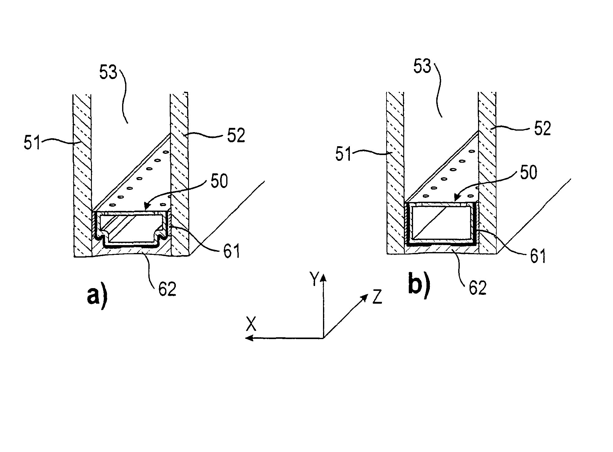
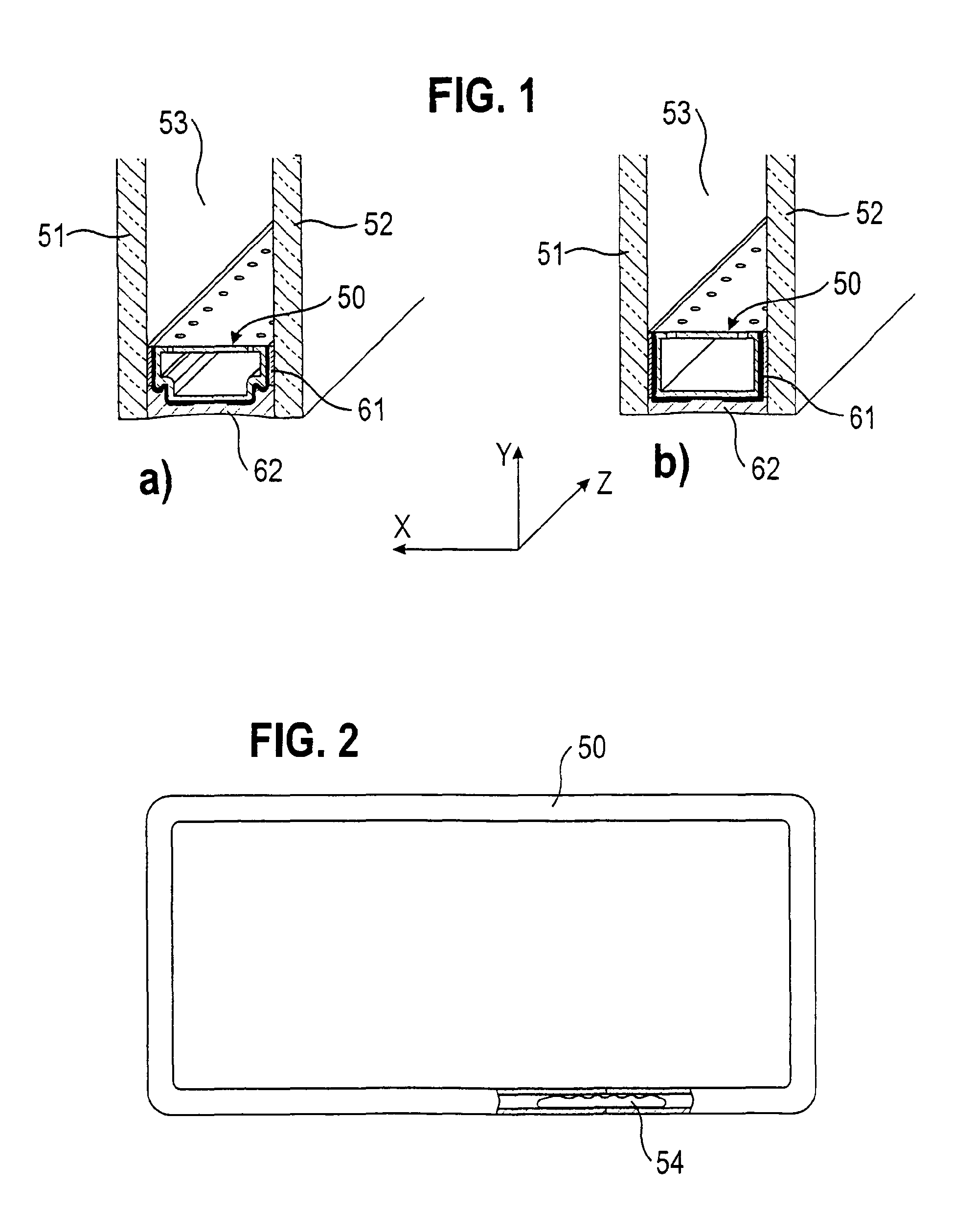
The filling gas should not be able to leak out from the space 153 between the panes over a long period of time.
In this process, the problem of wrinkle formation arises at the bends.

Method used


Image

  • Spacer profile and insulating pane unit having such a spacer profile
  • Spacer profile and insulating pane unit having such a spacer profile
  • Spacer profile and insulating pane unit having such a spacer profile

Examples


first embodiment

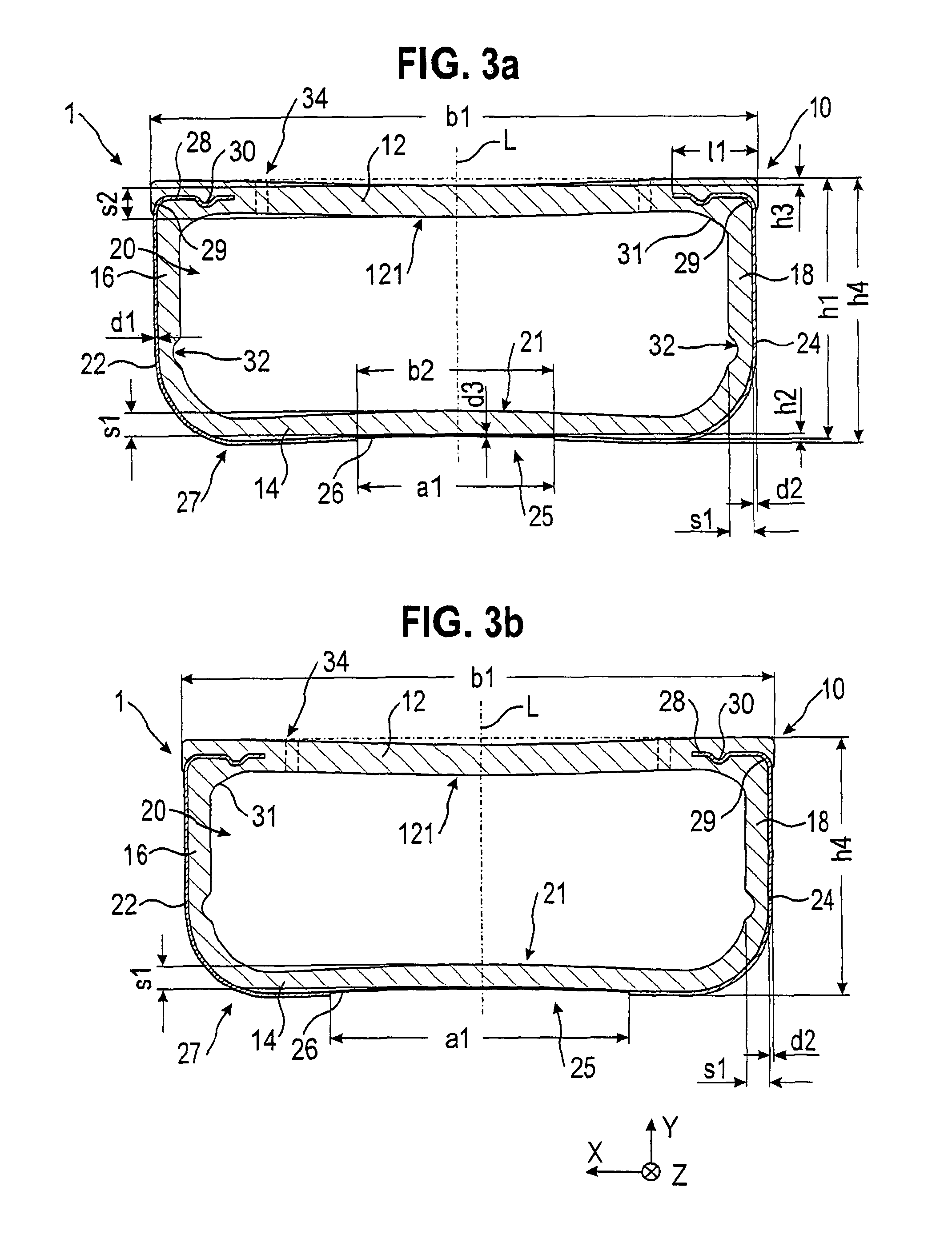
[0057]Furthermore, a spacer profile 1 will be described with reference to FIG. 3a). The spacer profile 1 is shown in FIG. 3a) in cross section perpendicular to a longitudinal direction Z, i.e. in the section in an X-Y plane, which is spanned by a transverse direction X, which is perpendicular to the longitudinal direction Z, and a height direction Y, which is perpendicular to the transverse direction X and the longitudinal direction Z. In the embodiment, the spacer profile 1 extends in the longitudinal direction Z with a symmetry plane L, which is centrally disposed in relation to the transverse direction X and extends parallel to the longitudinal direction Z and to the height direction Y.

[0058]The spacer profile 1 has a hollow profile body 10 made of a plastic material, which extends in the longitudinal direction Z with a constant cross-sectional shape and has a first width b1 in the transverse direction X and a first height h1 in the height direction Y. The hollow profile body 10...

fourth embodiment

[0098]The rest of the spacer profile 1 corresponds to what is shown in FIG. 3a). The fourth embodiment shown in FIG. 4b) differs from the embodiment shown in FIG. 4a) in that the first distance a1 is increased relative to the embodiment shown in FIG. 4a). The thermal conduction can be further reduced thereby.

[0099]The hereinafter-described fifth to twelfth embodiments each include, in particular, a diffusion-proof diffusion barrier 27, which is formed from the first reinforcing layer 22, the diffusion barrier layer 26 and the second reinforcing layer 24. Further, in all illustrated embodiments, the diffusion barrier layer 26 lies on the neutral line of spacer profile 1 during the bending about an axis parallel to the transverse direction X1. In the spacer profiles shown in FIGS. 5 to 14, none of the optional notches 32 and arches 21, 121 are shown for simplicity.

[0100]In the fifth embodiment shown in FIGS. 5a) and b), the extension segment 28 has a bend 29 of 90° corresponding to th...

seventh embodiment

[0102]Referring to FIGS. 7a) and b), a spacer profile 1 will be described, wherein in FIGS. 7c) and d) the areas surrounded by a circle in a) or b) are shown enlarged. In the embodiment shown in FIG. 7 the extension segments 28 do not protrude into the inner wall 12, but are provided on the outer side of the inner wall 12. The extension segments 28 are visible in a very advantageous position for bending property, certainly by a consumer when installed.

[0103]FIGS. 8a) and b) are cross sectional views of a spacer profile 1 according to an eighth embodiment. The eighth embodiment differs from the fifth embodiment in that the bend 29 is not a 90° bend, but rather a 180° bend, so that the part of the extension segment 28 that follows the bend 29 extends in the height direction Y. According to the sixth embodiment, a three-sided enclosure of a portion of the material of the hollow profile body 10 is thereby achieved, even though only one bend 29 is present. This leads to an improved bend...


PUM

PropertyMeasurementUnit
Angleaaaaaaaaaa
Poweraaaaaaaaaa
Poweraaaaaaaaaa

Abstract

A spacer profile for a spacer frame of an insulating pane unit includes a hollow profile body made of plastic with a chamber defined therein. The hollow profile body extends in a longitudinal direction and includes an inner wall, an outer wall, a first side wall and a second side wall, which are connected to the inner and outer walls to form the chamber. First and second reinforcing layers made of a metallic material respectively extend on the first and second side walls and partially on the outer wall so as to be spaced apart by a first distance. A diffusion barrier layer is formed directly on the outer wall between the first and second reinforcing layers and is connected thereto in a diffusion-proof manner in order to form a heat-insulating diffusion barrier. An insulating pane unit includes at least two panes with such a spacer frame disposed therebetween.

Description

CROSS-REFERENCE[0001]This application is the U.S. national stage of International Application No. PCT / EP2011 / 005405 filed on Oct. 26, 2011, which claims priority to German utility model application no. 20 2010 049 806.8 filed on Oct. 27, 2010.TECHNICAL FIELD[0002]The present invention concerns a spacer profile for use in insulating pane units having such a spacer profile and an insulating pane unit having such a spacer profile.RELATED ART[0003]Insulating pane units having at least two panes 151, 152 that are held spaced apart from one another inside the insulating pane unit are well-known (see FIG. 16). The panes 151, 152 are normally made of inorganic or organic glass or of other materials such as Plexiglas. The spacing of the panes 151, 152 is usually secured by a spacer frame 150, which is made of at least one composite material spacer profile 100. Composite material spacer profiles, which are also known as composite spacer profiles, are provided from a plastic profile and a meta...

Claims


Application Information

Patent Timeline
IPC IPC(8): E06B7/12E06B3/663E06B7/00
CPCE06B3/663E04C1/42E06B3/66304E06B3/66309E06B3/66319E06B7/12E06B2003/6638E06B3/667
Inventor CEMPULIK, PETERLENZ, JOERGSOMMER, PETRA
Owner TECHNOFORM GLASS INSULATION HLDG
Learn More