Control apparatus of vehicle

a technology of control apparatus and vehicle, which is applied in the direction of mechanical apparatus, electric control, machines/engines, etc., can solve the problems of unfavorable sticking, unfavorable supercharger performance, and uncertainty of valve sticking, so as to achieve easy and accurate judgment.

Active Publication Date: 2014-07-01
TOYOTA JIDOSHA KK
View PDF25 Cites 2 Cited by
  • Summary
  • Abstract
  • Description
  • Claims
  • Application Information

AI Technical Summary

Benefits of technology

[0014]In view of the aforementioned problems, it is therefore an object of the present invention to provide a control apparatus of a vehicle, which efficiently detects the sticking while preventing the sticking of the various changeover valves related to the operations of the plurality of superchargers and which can realize a preferable fail-safe.Means for Solving the Subject
[0035]Moreover, the specification of the opening / closing state by the specifying device facilitates the specification of the changeover valve which is in the sticking state, regardless of the number of the changeover valves provided for the supercharging system. Thus, it is easy and possible to take a desirable fail-safe measure in cases where it is judged that at least one portion of the changeover valves is in the sticking state.

Problems solved by technology

However, in the technique disclosed in the patent document 1 and the patent document 2, the exhaust changeover valve is forcibly driven during engine operation so as to prevent the sticking of the exhaust changeover valve; however, from the practical viewpoint, there is no guarantee that the sticking is surely avoided by this type of forcible driving.
On the other hand, from the viewpoint of the sticking detection, in any of the aforementioned techniques, the sticking is detected during engine operation, and the sticking of the exhaust changeover valve can be a factor causing an unexpected performance degradation of the superchargers.
However, the various changeover valves also have the potential for the sticking in the same manner, and it is uncertain which valve will have the sticking.

Method used


Image

  • Control apparatus of vehicle
  • Control apparatus of vehicle
  • Control apparatus of vehicle

Examples


embodiment

Operations of Embodiment

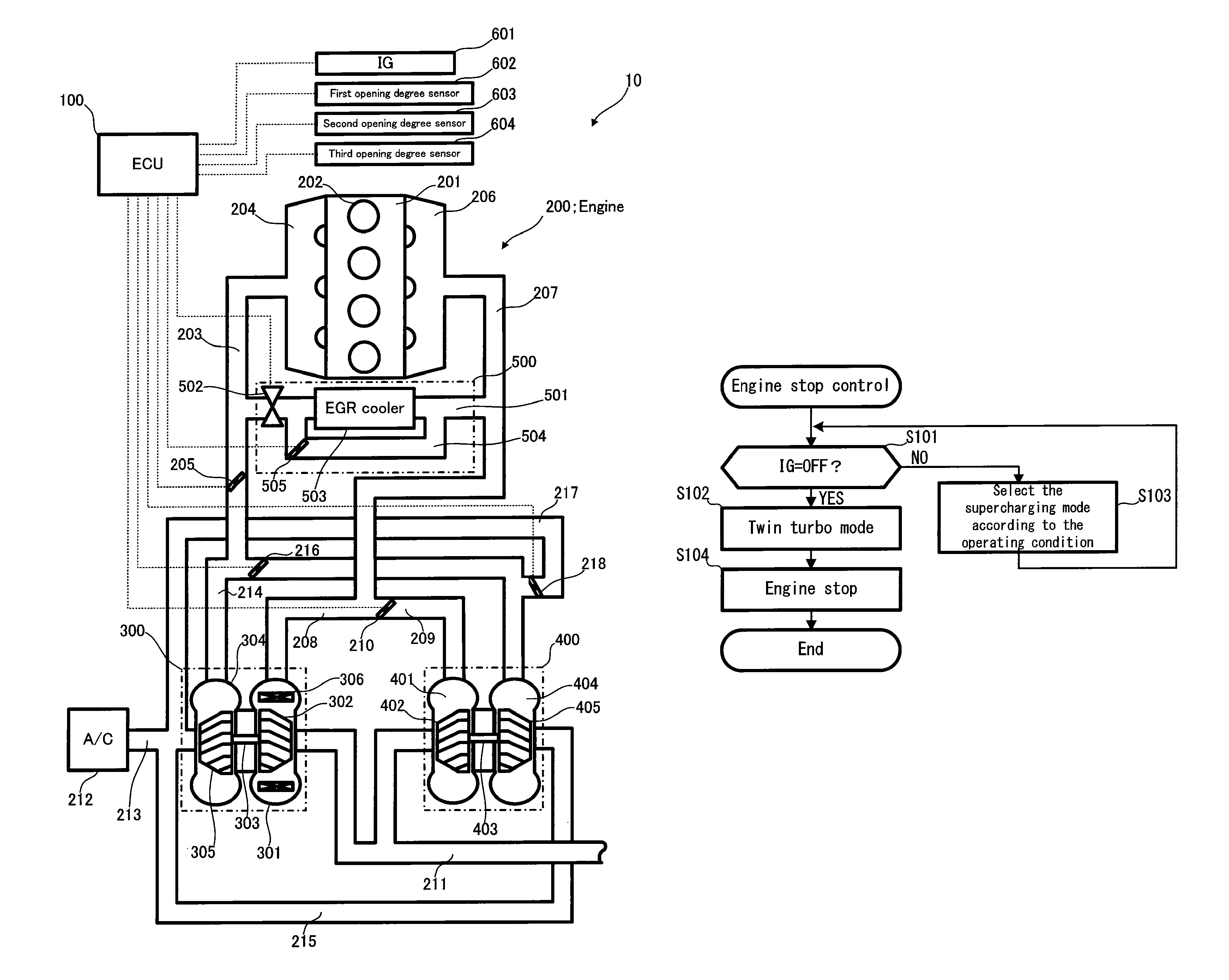
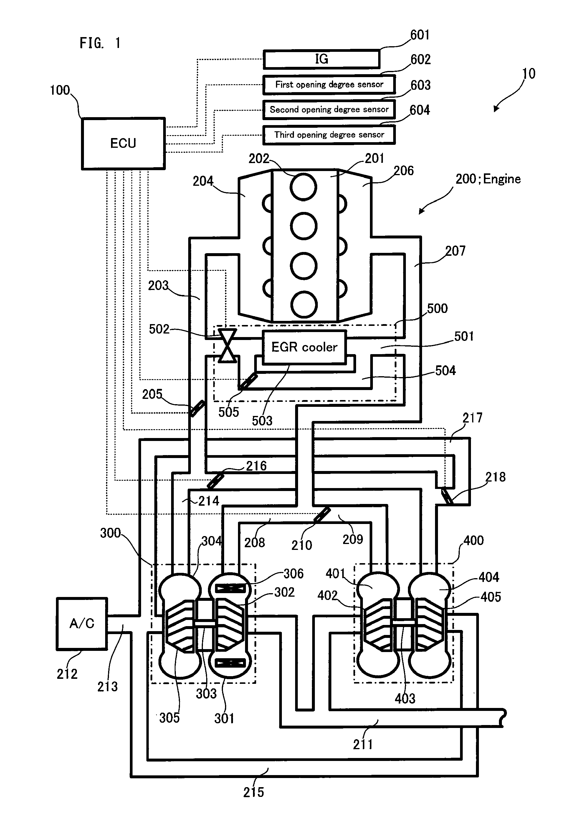
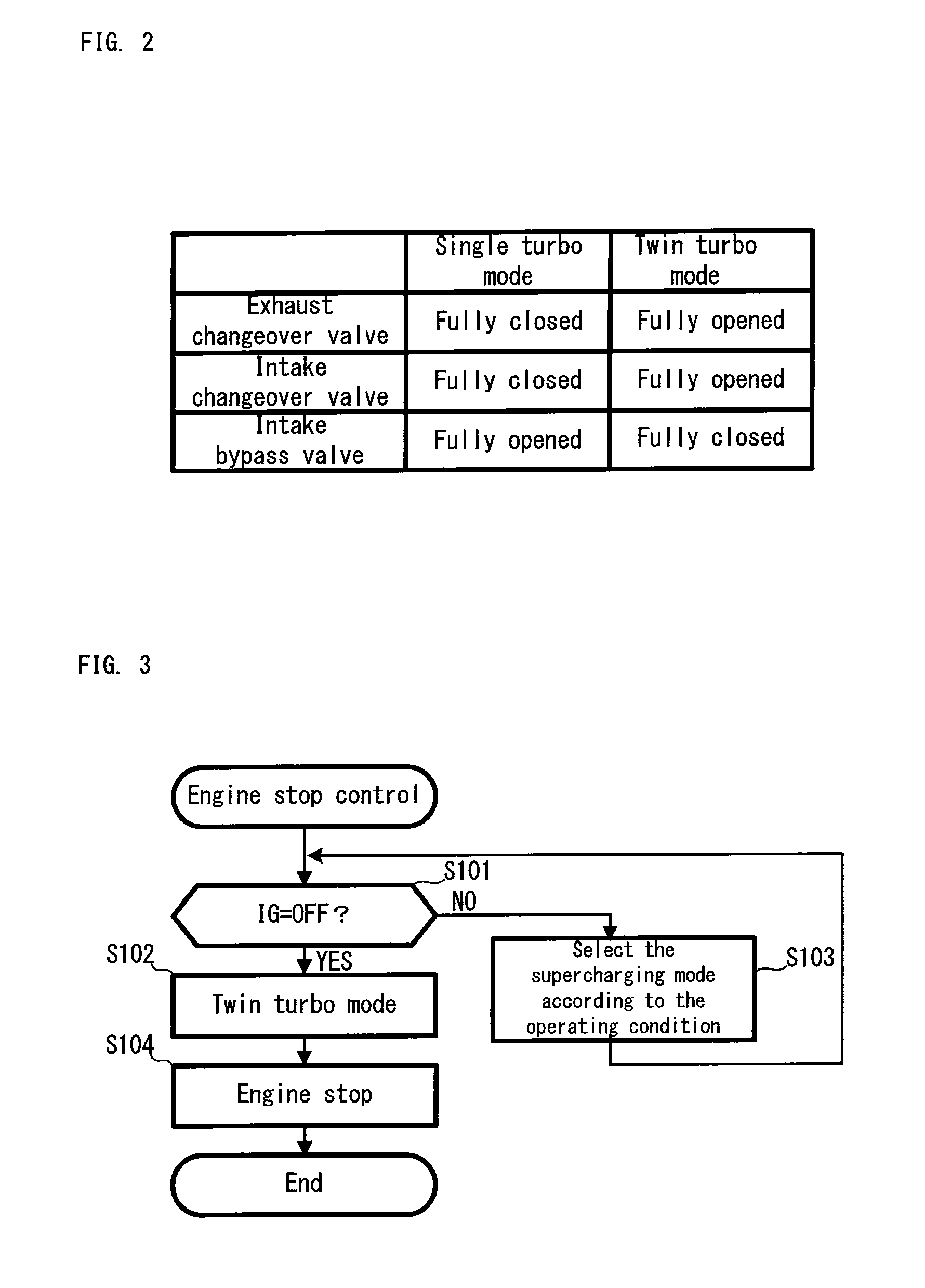
[0085]In the engine system 10, two types of supercharging modes are selectively changed by the cooperation control of the exhaust changeover valve 210, the intake changeover valve 216 and the intake bypass valve 218. Now, with reference to FIG. 2, an explanation will be given on a correspondence relation between the opening / closing state of each changeover valve and the supercharging mode. FIG. 2 is a list showing the correspondence relation.

[0086]As shown in FIG. 2, if the exhaust changeover valve 210 and the intake changeover valve 216 adopt the fully-closed opening degree and the intake bypass valve 218 adopts the fully-opened opening degree, then, a single turbo mode is realized.

[0087]In the single turbo mode, the exhaust changeover valve 210 has the fully-closed opening degree, and thus the supply of the exhaust air to the secondary turbine 402 is cut off. Thus, the secondary compressor 405 coupled with the secondary turbine 402 via the turbine rotating ...


PUM


Abstract

In a vehicle, which is provided with: a primary turbo and a secondary turbo, each of which is of an exhaust driven type; an exhaust changeover valve and an intake changeover valve, which are placed in a secondary exhaust passage and a secondary intake passage corresponding to the secondary turbo, respectively; and an intake bypass valve placed in an intake bypass passage, an ECU sets the opening / closing state of each changeover valve to an opening / closing state corresponding to a twin turbo mode at the time of engine stop, and it uses the drive control of each changeover valve which is necessitated in the transition to a single turbo mode at the engine start, thereby performing the sticking detection of the changeover valve at the same time.

Description

[0001]This is a 371 national phase application of PCT / JP2009 / 051187 filed 26 Jan. 2009, the contents of which are incorporated herein by reference.TECHNICAL FIELD[0002]The present invention relates to a control apparatus of a vehicle having a supercharging system such as a twin turbo.BACKGROUND ART[0003]As this type of apparatus, there has been suggested an apparatus for preventing an exhaust changeover valve from sticking (e.g. refer to a patent document 1). According to an abnormality prevention controller of an engine with a supercharger disclosed in the patent document 1, if a valve stick state is predicted by a valve stick state predicting device on the basis of the quantity of state or the operating condition of an engine and a system, the exhaust changeover valve is forcibly driven. Thus, next time the exhaust changeover valve is closed, a contact position between a valve outer circumferential portion and a housing inner circumferential portion changes, so that the valve stic...

Claims


Application Information

Patent Timeline
Patent Type & Authority Patents(United States)
IPC IPC(8): F02B33/44F01N13/10F02B33/00F02B37/00F02B37/007F02B37/02F02B37/12F02B37/16F02D9/02F02D9/04F02D41/00F02D41/04F02D41/06F02D41/22F02M25/07
CPCF02B37/007F01N13/107F02B37/02F02B37/12F02B37/16F02D9/02F02D9/04F02D41/0007F02D41/042F02D41/062F02D41/22F02M25/0707F02M25/0711F02M25/0728F02M25/0731Y02T10/144Y02T10/40F02M26/05F02M26/08F02M26/25F02M26/28Y02T10/12
Inventor OYAGI, HIROSHIYAMASHITA, YOSHIOIWATANI, KAZUKIAOYAMA, TARO
Owner TOYOTA JIDOSHA KK
Why Eureka
Try Eureka