Fuselage section of an aircraft and method for the production of the fuselage section

a fuselage section and aircraft technology, applied in the field of fuselage sections of aircraft, can solve the problems of reduced usable cabin diameter inside the fuselage section, reduced usable cabin fixtures, and still stiff structure of the fuselage section produced, so as to reduce the thickness reduce the weight, and increase the interior space of the fuselage section available for cabin fixtures

Active Publication Date: 2014-07-01
AIRBUS OPERATIONS GMBH
View PDF9 Cites 0 Cited by
  • Summary
  • Abstract
  • Description
  • Claims
  • Application Information

AI Technical Summary

Benefits of technology

[0010]The problem to be solved by the present application is to make available a fuselage section of an aircraft and a method of producing the fuselage element from fiber composite materials which eliminates the disadvantage of stiffening structures that project into the inside volume of the fuselage section.
[0035]The fuselage section is further characterized by another useful feature in that the skin thickness D at the points of intersection between the second and third fibers is greater than in the areas between the points of intersection, which ultimately has the effect that the fuselage section skin has an outer surface comprising concave structures. The concave structures are formed especially in the geometric mean of the lattice faces generated by the lattice points.
[0036]Outer surfaces of an aircraft fuselage with this type of structure are able to noticeably reduce the air resistance of a flying aircraft, for example, by inducing a turbulent flow in the near-surface boundary layer. To this end, the dimensions of the concave structures and thus the arrangement of the lattice of the stiffening structure must be adapted to an air flow speed, for example, to the typical cruising speed, of the airplane involved and to local geometric requirements of the shape of the fuselage section.
[0039]Accordingly, it possible to markedly reduce the skin thickness of fuselage sections in comparison with the stringerless and ribless fuselage sections known from the prior art. More specifically, the inside space of fuselage sections available for cabin fixtures is increased as compared to the inside space of the fuselage sections known from the prior art. The fuselage sections can be manufactured so as to have a lower weight and a higher flexural and torsional stiffness, which leads to higher cabin pressure differences and, as a result, to higher cruising altitudes and, ultimately, to a reduced fuel consumption. On the other hand, it is possible to provide the fuselage sections with the inside volume typically required today while reducing the outside diameter of the fuselage sections and the entire aircraft fuselage, which in turn leads to a reduction of the air resistance of the aircraft, to a reduction of weight, and thus to lower operating costs and ultimately to a reduction of the environmental impact.

Problems solved by technology

Since the stiffening elements are traditionally disposed almost exclusively on the inner surface of the outer skin and, depending on the construction, typically have a depth of 5-25 cm, these elements require considerable installation space and ultimately reduce the usable cabin diameter inside the fuselage section.
The disadvantage of this method is that the fuselage section produced still has stiffening structures that project into the inside volume of the fuselage section.

Method used


Image

  • Fuselage section of an aircraft and method for the production of the fuselage section
  • Fuselage section of an aircraft and method for the production of the fuselage section
  • Fuselage section of an aircraft and method for the production of the fuselage section

Examples


Embodiment Construction

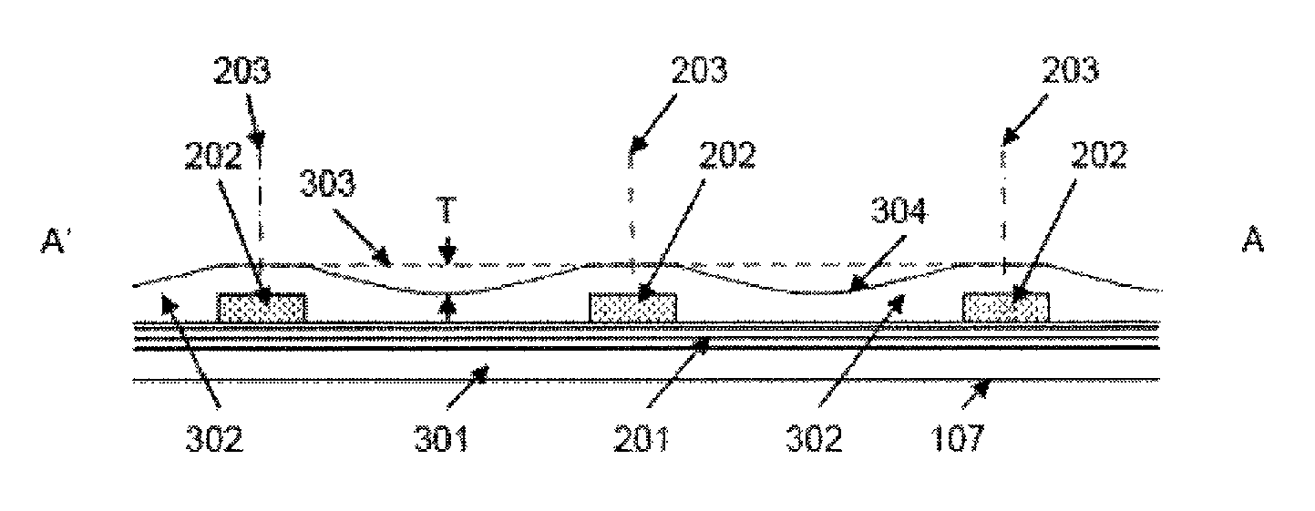
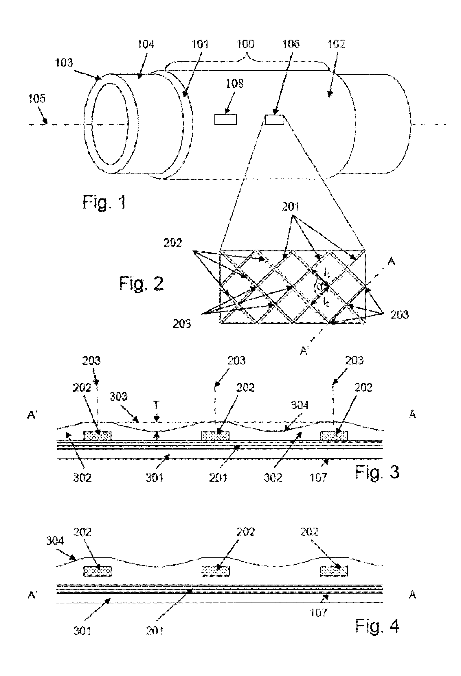
[0047]FIG. 1 shows a schematic representation of a hollow cylinder-shaped fuselage section 100 of an aircraft with its fuselage section skin 101, which fuselage section has been applied to a construction mold 103 and has already been cured in an autoclave process. The construction mold 103 is a hollow cylinder with an unstructured construction mold surface 104. The construction mold, the fuselage section 100 and the fuselage section skin 101 have a common longitudinal axis 105.

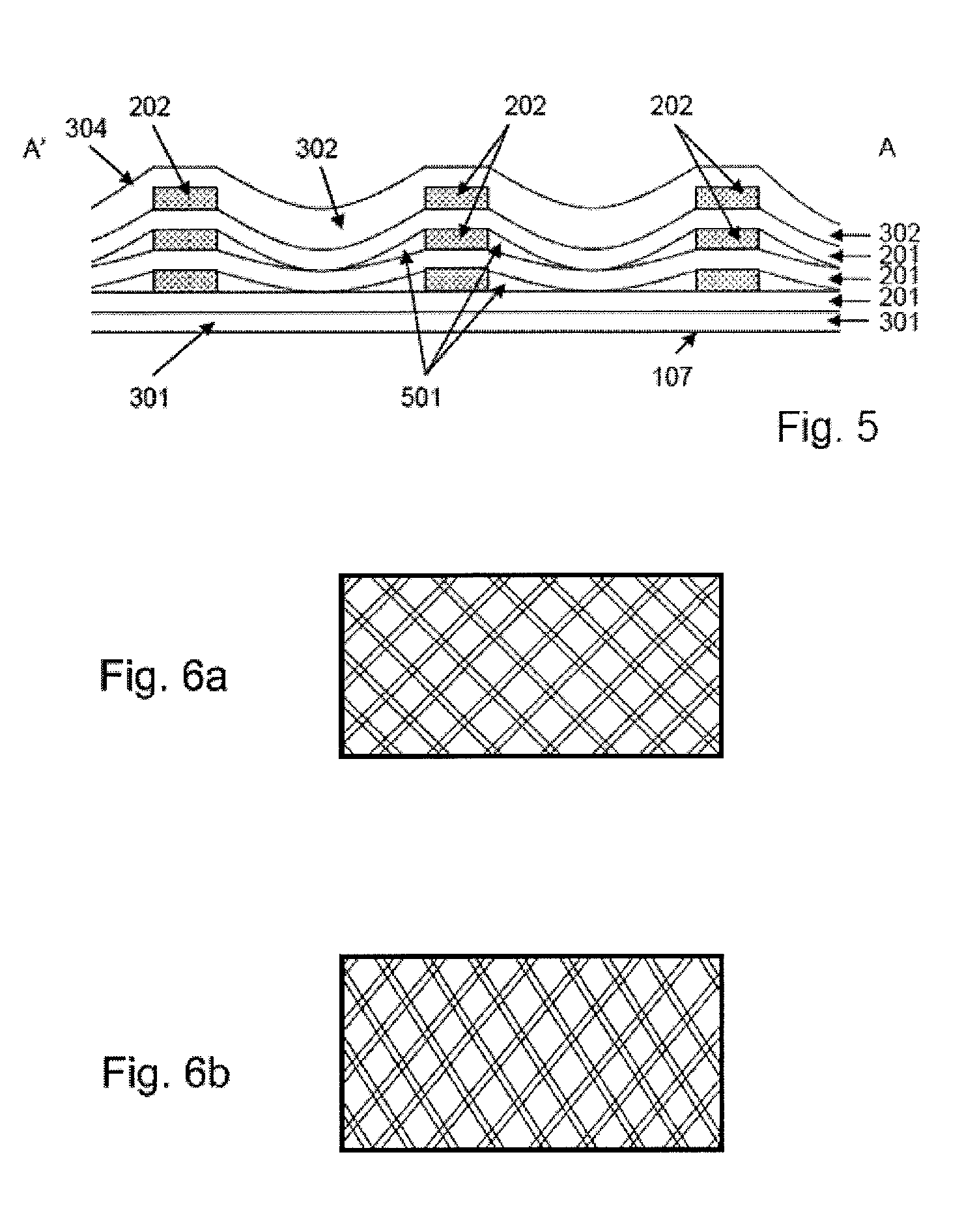
[0048]To form the shown cured fuselage section skin 101 with an integral stiffening structure, resin-impregnated fibers are applied, so as to be oriented in different fiber orientations, to the construction mold surface 104 which currently has no depressions, with the fiber orientations of the fibers that form the stiffening structure being different from the fiber orientations of the other fibers. To this end, first a continuous full-surface inner layer 301 of the fuselage section skin 101, the inner layer co...


PUM

PropertyMeasurementUnit
lattice angleaaaaaaaaaa
depthaaaaaaaaaa

Abstract

In accordance with the method, an inside layer of a fuselage section skin made from first fibers is placed on a manufacturing surface, the first fibers being placed in one or more first fiber directions. On the inside layer, a stiffening structure is formed from stiffening fibers, the stiffening fibers being placed in one or more stiffening fiber directions. An outside layer of the fuselage section skin, comprising fourth fibers, is placed on the stiffening structure formed from stiffening fibers, the fourth fibers being placed in one or more fourth fiber directions. The stiffening structure is designed and developed in such a way that the fuselage section does not require an additional stiffening structure, is connected with the fuselage section skin, and comprises the inside layer, the stiffening structure, and the outside layer; in particular, an additional stiffening structure in the form of stringers and frames is not required.

Description

CROSS REFERENCE TO RELATED APPLICATION[0001]This application claims priority to U.S. Provisional Application No. 61 / 353,689 filed on Jun. 11, 2010, which is incorporated herein by reference in its entirety.BACKGROUND[0002]1. Field[0003]This application relates to a fuselage section of an aircraft, in particular a hollow cylinder-shaped or barrel-shaped, stringerless and ribless fuselage section of an aircraft, and to a method of producing the fuselage section from fiber composite materials.[0004]2. Brief Discussion of Related Art[0005]It is generally known that a fuselage of an aircraft can be produced by joining a plurality of pre-manufactured fuselage sections. Fuselage sections of this type typically comprise an outer skin and stiffening elements that are connected to the inner surface of the outer skin. The structural stability required of a fuselage section is achieved through the interaction of the composite structure of outer skin and stiffening elements. The stiffening eleme...

Claims


Application Information

Patent Timeline
Patent Type & Authority Patents(United States)
IPC IPC(8): B64C1/00B32B37/16B29C70/30
CPCB29D99/001Y02T50/433Y02T50/43B64C1/068B29L2031/3082B64C2001/0072B29C70/202Y02T50/40
Inventor FRAUEN, HOLGERGOEHLICH, ROBERT ALEXANDER
Owner AIRBUS OPERATIONS GMBH
Why Eureka
Try Eureka