Device for separating and collecting fluid in gas from a reservoir

Inactive Publication Date: 2014-07-08
AKER SOLUTIONS AS
View PDF6 Cites 6 Cited by
  • Summary
  • Abstract
  • Description
  • Claims
  • Application Information

AI Technical Summary

Benefits of technology

[0053]Compared to the conventional draining of a subsea liquid separator with an associated liquid collecting volume and the level contro

Problems solved by technology

In contrast to the prior art, involving draining with the aid of electrically operated pumps or gravity and flushing of sand using liquid delivered from pumps, the requirement for a successful result using compressed gas is, howev

Method used


Image

  • Device for separating and collecting fluid in gas from a reservoir
  • Device for separating and collecting fluid in gas from a reservoir
  • Device for separating and collecting fluid in gas from a reservoir

Examples


Embodiment Construction

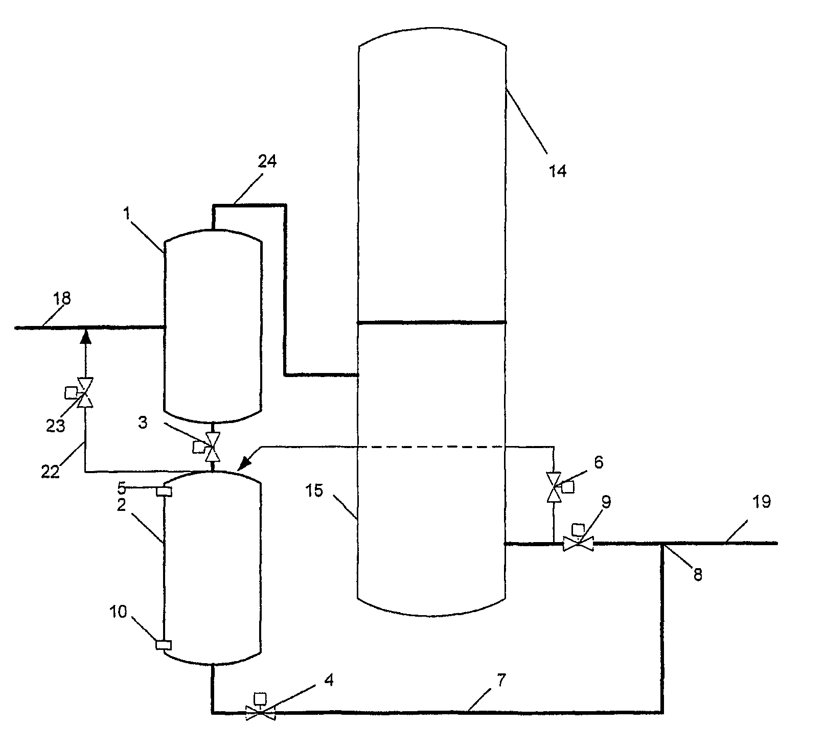
[0061]For a clearer understanding of the present invention, reference is made to FIG. 3 and the meaning of the reference numerals can be seen from the list in Table 4 below:

[0062]

TABLE 41Liquid separator2Liquid collector3Valve4Valve5Upper level sensor6Valve for compressed gas for draining of the liquid collector7Outlet pipe for liquid8Mixing point for liquid and gas9Choke valve for compressor outlet, may optionally have fixedchoking10Lower level sensor11Valve for draining inactive compressor and suitably adjustedchoke valve12Valve for inlet to compressor13Drainage valve for liquid from compressor14Compressor motor15Compressor16Valve for flushing gas to liquid separator17Valve for flushing gas to liquid collector18Inlet pipe for wet gas19Outlet pipe for wet gas20Shut-off valve for inlet21Shut-off valve for outlet22Vent pipe23Vent valve24Pipe25-25″′Drainage valves for horizontal compressor26Drainage valve for motor of horizontal compressor30Dividing plate31Downpipe from secondary clea...


PUM

PropertyMeasurementUnit
Timeaaaaaaaaaa
Pressureaaaaaaaaaa
Mixtureaaaaaaaaaa

Abstract

A device for separating and collecting liquid in gas from a reservoir, which is attached to processing equipment (14, 15) for gas, said gas being delivered to the processing equipment from the device via an inlet pipe (24) to the processing equipment and the collected liquid is removed periodically from the device via liquid outlet pipe (7). The device is formed of a liquid separator (1) and a liquid collector (2) which are two separate chambers, and which are connected to each other via a valve (3), and that for draining of the collected liquid, the liquid collector (2) is connected to an outlet pipe (19) from the processing equipment via an intermediate valve (6), draining taking place with the aid of compressed gas which via the intermediate valve (6) is supplied from the processing equipment, or alternatively from onshore or a platform, from a gas pipe or a well stream gas pipe on the seabed or the like.

Description

[0001]The present invention utilises the energy in compressed gas for draining and sand flushing, with swirling of sand and other particles, of a subsea liquid separator with associated liquid collector.BACKGROUND OF THE INVENTION[0002]To protect processing equipment, and in particular gas processing equipment, against unacceptable inflow of liquid, which also may contain sand and other particles, hereafter referred to by the collective term “sand”, a liquid separator is as a rule placed upstream of the equipment. Liquid and sand are thus collected such that gas and liquid, with sand, can then be treated separately.[0003]Such protection of subsea compressors against too great an inflow of liquid and sand is previously known, and is generally effected by placing a liquid separator upstream of the compressor, such that liquid and sand can be separated from the well stream, collected and pumped into the gas transport pipe at a point downstream of the compressor, or optionally that the ...

Claims


Application Information

Patent Timeline
IPC IPC(8): B01D45/00B01D45/18
CPCE21B43/36F04D25/0686F04D31/00E21B43/35
Inventor SKOFTELAND, HAKONSTINESSEN, KJELL OLAV
Owner AKER SOLUTIONS AS
Why Eureka
Try Eureka