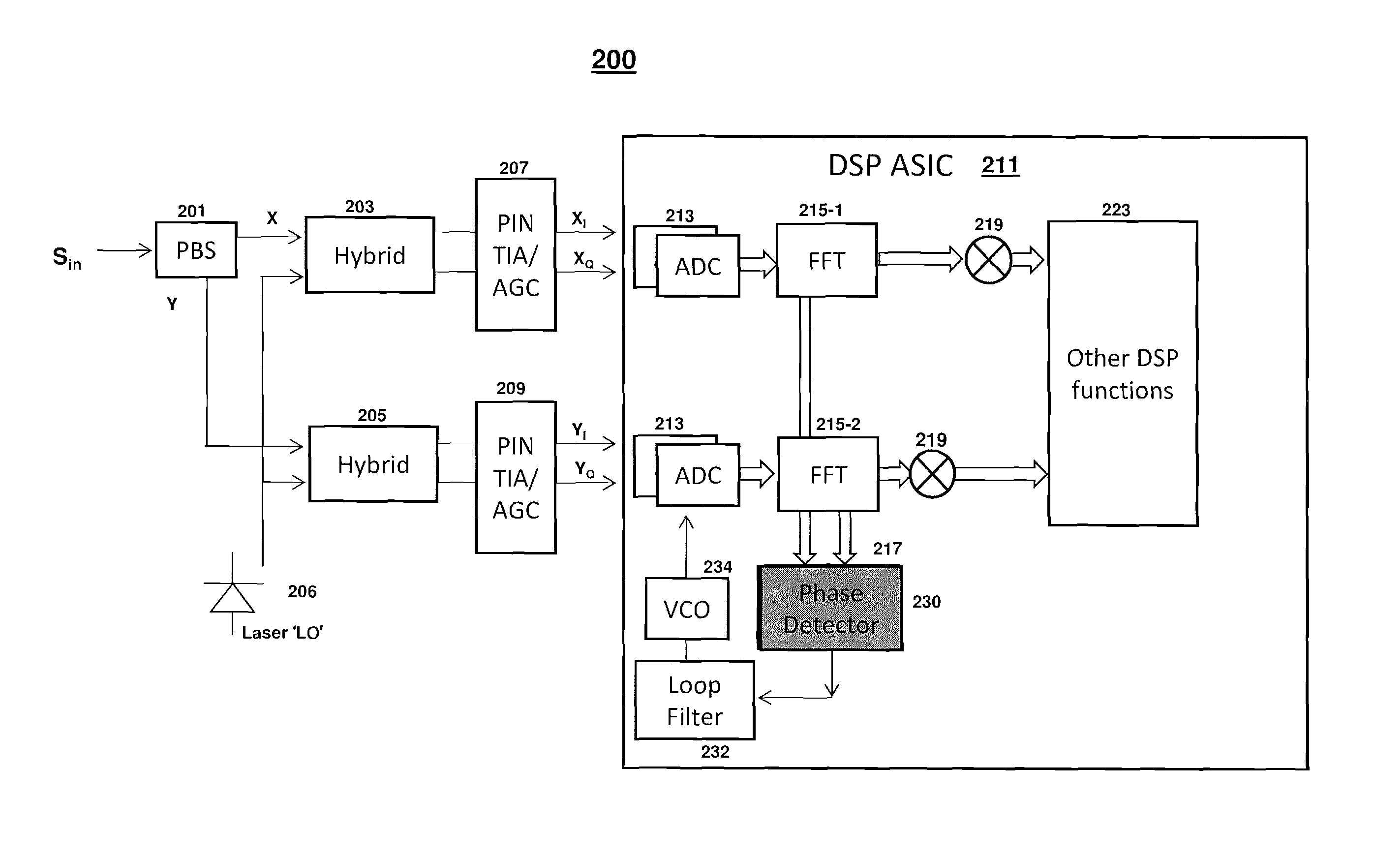
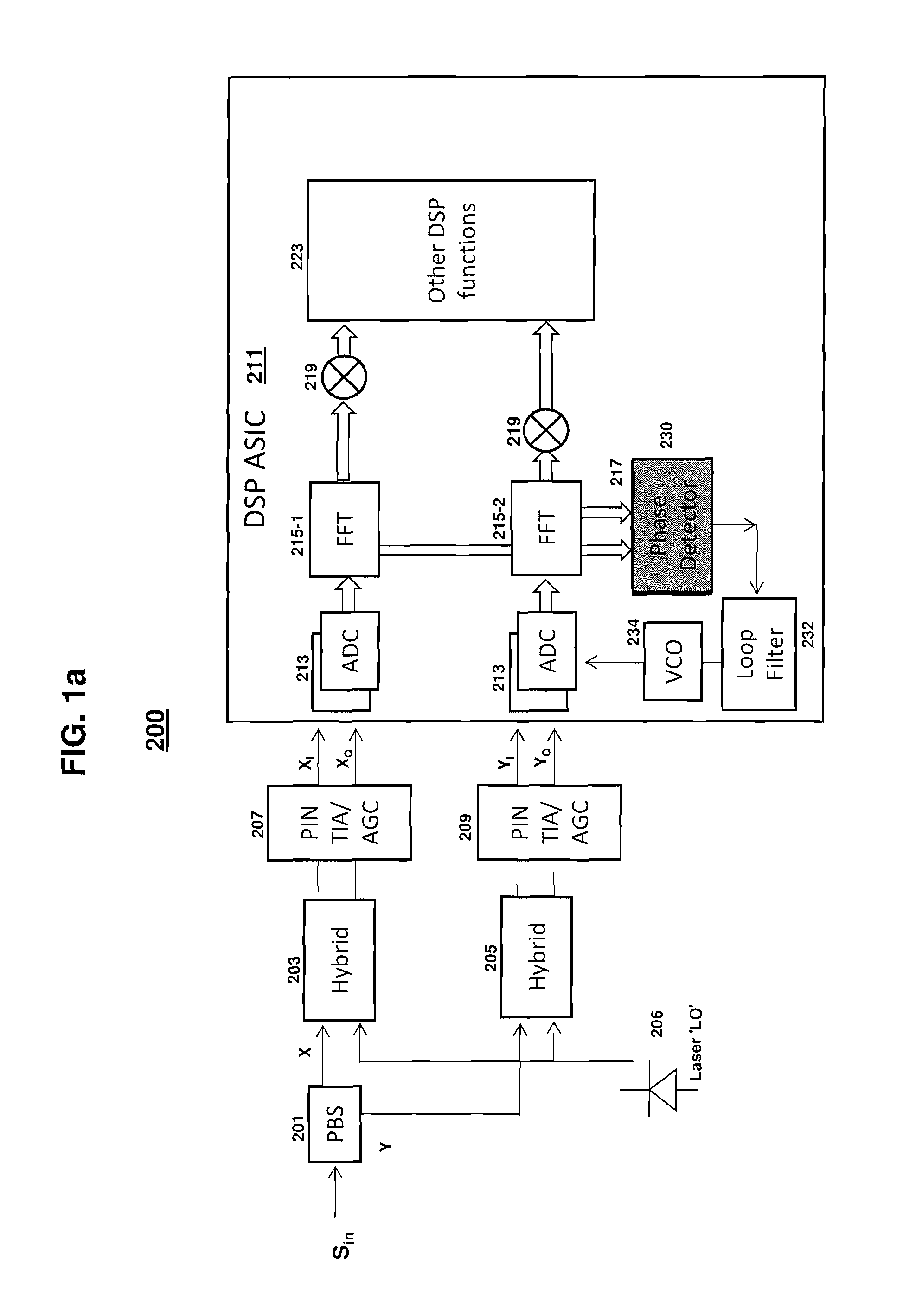
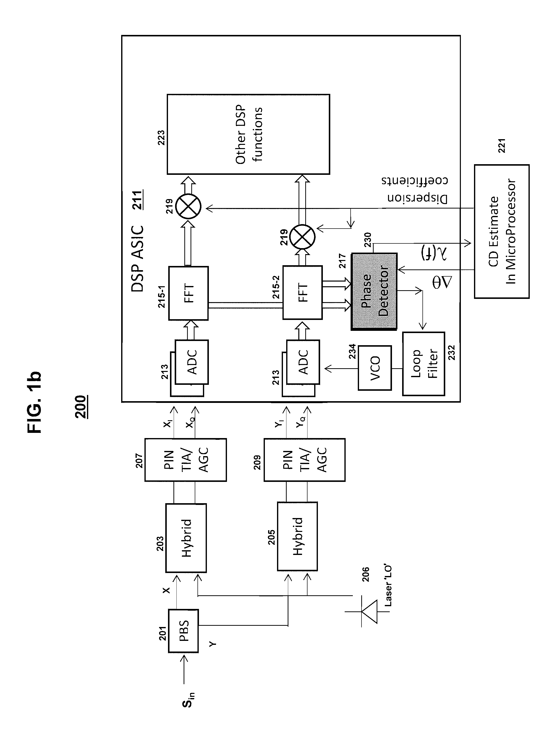
Accordingly, in some known systems
clock recovery cannot be performed until the impairments are compensated for in the receiver, which can be very difficult for large amounts of
distortion resulting in unnecessary
delay in initializing the receiver.
Chromatic dispersion is a result of different spectral components of an optical signal propagating at different speeds along an
optical fiber, resulting in an undesirable temporal spreading of the optical signal.
PMD occurs due to the different polarization
modes (X and Y polarization components) of the optical signal propagating along the
fiber at different speeds and is caused by environmental effects and asymmetries in the
optical fiber, which are often random, unpredictable and can vary over time.
Due to the random and unpredictable nature of PMD, PMD often cannot be easily determined or compensated for in a conventional optical communication system.
In practice, however, implementing such DCFs and other known dispersion compensating techniques and components in the optical communication system undesirably increases the size and complexity of the system, and can be cumbersome and expensive.
One challenge related to these techniques, however, is that without the use of DCFs, a coherent optical receiver should be designed to compensate for a large chromatic dispersion, such as values as high as 51,000 ps / nm or higher.
Another challenge is that since the received signal is affected by both chromatic dispersion and PMD, it is more difficult to singularly estimate the effects of either one.
In a system with potentially large chromatic dispersion and PMD, it is very difficult to accurately and efficiently estimate these effects in the receiver, thus seriously degrading performance of the optical communication system.
These solutions, however, are limited in that in many systems, especially switched systems in which the signal may travel via one of several different links, the chromatic dispersion effects cannot be easily known or determined in advance because each link
scenario has a different chromatic dispersion, or the
adaptive filter cannot be easily or efficiently updated.
For each iteration, the step of calculating the chromatic dispersion coefficients results in even greater complexity.
Additionally, there is added
delay in such systems due to the time required for the acquired signal to be allocated for the chromatic dispersion scanning steps discussed above.
Additionally, the chromatic dispersion
estimation methods discussed above fail to discriminate between actual chromatic dispersion effects and the effects of the second and higher order components of PMD present in the optical communication system.
If the estimated chromatic dispersion in these known methods includes the effects of second order PMD, the receiver sensitivity can be seriously corrupted.
Another
disadvantage of such scanning methods is that the chromatic dispersion cannot be accurately estimated until the
clock recovery loop is locked.
The above scanning methods typically only partially compensate for the chromatic dispersion in order to recover the timing signal.
These methods, however, are inefficient and unreliable since the
clock recovery loop cannot lock with a satisfactory sensitivity until the signal impairments are fully compensated.
This requires a high degree of complexity in the receiver and results in considerable increase in
processing time and unsatisfactory
delay in initializing the receiver.
Furthermore, for optical communication systems with large PMD resulting in a high DGD such as one half
symbol period (i.e., T / 2, where T is the
symbol period), the above receiver techniques do not enable satisfactory sensitivity of clock timing
recovery functionality with respect to the PMD effects of the received signal, thus resulting in poor system performance.
Accordingly, the clock phase detection on either of the X-polarization signal or the Y-polarization signal of the two uncorrelated signals will cancel each other out and result in a modem failure in the receiver.
The known techniques, however, lead to clock
recovery loop lock points of the signal that are a function of the detected PMD conditions in the
fiber channel.
Further, the time-varying nature of the PMD conditions result in clock
jitter that can accumulate over multiple regeneration nodes in known systems and cause adverse affects in the clock phase detection circuitry.