Syringe with inspection window

a technology of syringe and inspection window, which is applied in the field of syringe with inspection window, can solve the problems of accidental contact of the plunger shaft—touch contamination, infection of the patient, and difficulty in handling a larger syringe with only one hand, so as to prevent accidental separation, reduce the extent of time and intensity, and be more stable and safer to work with or store.

Inactive Publication Date: 2014-07-15
GRAY ROBIN SCOTT
View PDF16 Cites 23 Cited by
  • Summary
  • Abstract
  • Description
  • Claims
  • Application Information

AI Technical Summary

Benefits of technology

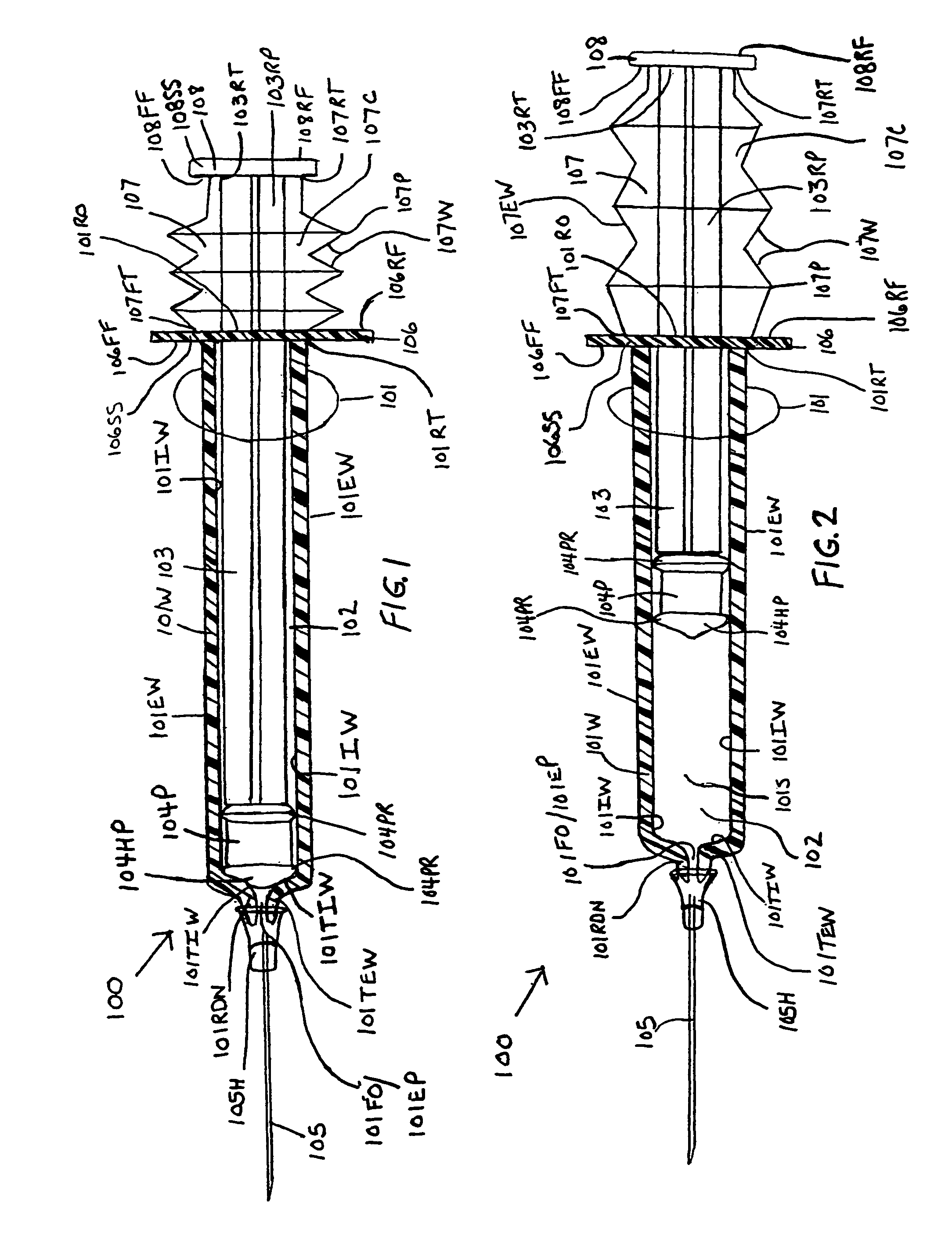
[0044]When the end cap contaminant shield is used, the forward end terminus of the end cap walls function to prevent accidental separation of the plunger member and syringe barrel by abutment of the forward end terminus of the end cap perpendicularly extending walls with the forward end terminus of the plunger separation of the plunger member from the syringe barrel by abutment of the forward face surface of the shield with forward end terminus of the plunger shaft or piston. Second, the shield functions as a temporary dam or barrier to fluids that may escape the syringe cavity due to piston failure through its deformation and allow fluids to pass between the piston and inside cavity wall.
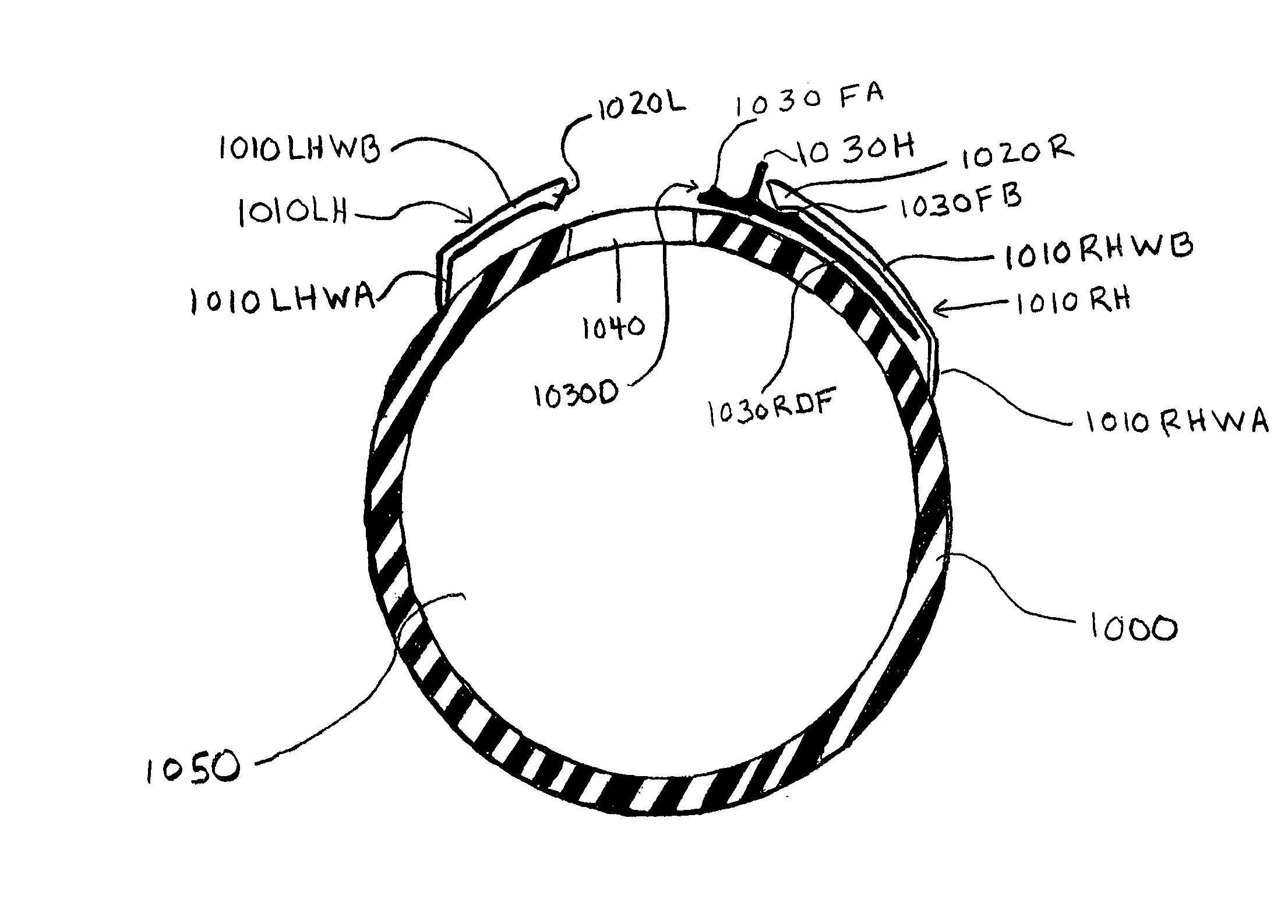
[0045]In the sixth embodiment of the instant invention, as shown in FIGS. 17A-23, it is an object to provide a new and improved syringe having an inspection window for viewing medications or other materials within the cavity of a syringe barrel having a colored, opaque, darkened, amber, smoked, tinted, syringe barrel—or polarizing filters or materials having light polarizing properties can be used to manufacture the syringe barrel and other syringe components to cancel particular components of light; or polarizing filters or materials can be applied to the syringe barrel to cancel particular components of light. The function of the colored, opaque, smoked, darkened, amber, tinted, or polarized syringe barrels of the instant invention is to filter light and limit the extent in both time and intensity that external degrading components, such as visible light waves, infrared waves, or ultraviolet light waves, etc., can interact with a medication or other materials within the syringe barrel that are susceptible to light degradation. The inspection site window can run the longitudinal length of the syringe barrel. If the material being drawn into the syringe is particularly prone to degradation due to light exposure, the inspection site or window may also be tinted or colored filters to have a lighter color or tint than the syringe barrel, or polarizing filters can be used to cancel particular components of light. The volume measuring indicia can be printed over, on, or adjacent to the inspection window. In this design the rim of the piston is used in conjunction with the printed measuring indicia used for the inspection window to aid in drawing the proper volume of material into the syringe barrel cavity, for viewing the volume of material in the syringe barrel, and for ejecting the proper volume of material from the syringe barrel cavity. Additionally, the inspection window may have magnifying properties to further aid the user in measuring the volume of material in the syringe barrel.
[0046]The inspection window can also be provided with a sliding door, or hinged door, which can be slid or pivoted open to expose the inspection window and slid or pivoted closed to conceal the inspection window. The door functions to cover the inspection window and aids in protecting the contents of the syringe from light exposure by way of the inspection window. This is particularly important for materials, such as medications, that are sensitive to light exposure and are being exposed to light for an extended period of time—such as when the syringe carrying the material is being used in a syringe pump for delivering medication, or being transported from one location to another, or where the material is being transferred from one container to another container. It also protects where medications or materials being carried in the syringe are more susceptible or prone to degradation when exposed to light of greater intensities or greater energies, It protects the materials against light waves of different frequencies or against specific components of light.
[0047]As an alternative to the sliding door or the hinged door, adhesive foil, tape material, or smoke or dark colored film that...

Problems solved by technology

Although not encouraged, inadvertent contact of the plunger shaft—touch contamination—typically occurs with the hands, fingers, or gloves during the preparation of a solution.
While a handle portion is usually located on the rearward end portion of the plunger to aid an individual in sliding the plunger into and out of the syringe barrel, larger syringes are typically difficult to handle using only one hand, or even both hands, because of the syringe size, plunger length, and friction created by surface area contact between the internal wall surfaces of the syringe barrel and the plunger piston surface.
These contaminants may also fall into the rearward end opening of the syringe barrel and come in contact with and deposit on the inner surfaces of the syringe barrel.
Infusion of a pathogen or other contaminates into a patient has the potential to cause infection in the patient.
Infusing or injecting solutions containing contaminate particulate matter into a patient has the potential of introducing thrombi and vessel blockage.
Syringes and plungers currently in use do little to discourage the introduction of contaminants onto the plunger shaft and inner syringe barrel surface.
The current syringes also suffer from problems of piston failure or detachment of the piston from the forward end of the plunger shaft causing loss of the seal between the piston and the inner surfaces of the syringe barrel.
When this occur...

Method used


Image

  • Syringe with inspection window
  • Syringe with inspection window
  • Syringe with inspection window

Examples


second embodiment

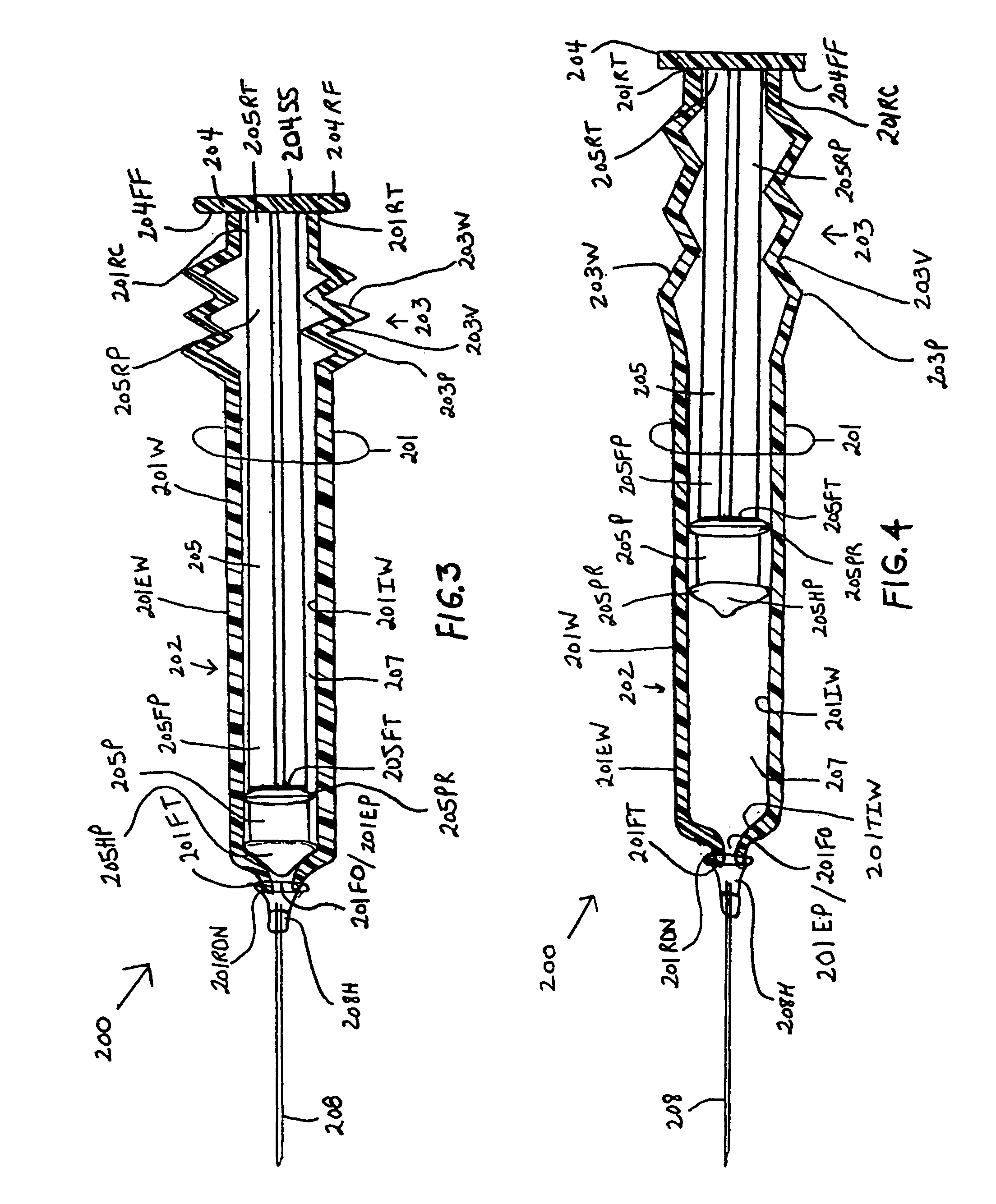
[0109]the instant invention, as shown by FIG. 3, illustrates a new and improved syringe 200 formed of a cylindrical syringe barrel 201 and a cylindrical plunger member 205. The syringe barrel 201 is formed with a straight segment 202 and a corrugated segment 203. The straight segment 202 is located on the forward end section of the syringe barrel 201 and the corrugated segment 203 is located at the rearward end section of the syringe barrel 201. The rearward end terminus 201RT of the syringe barrel 201 is molded to at least one surface of a plunger handle member 204. The at least one surface includes, but is not limited to, the forward face surface 204FF, the rearward face surface 204RF, and the side surface 204SS. The rearward end terminus 205RT of the plunger shaft 205 is centrally molded to the forward face surface 204FF of the plunger handle member 204. A rearward end portion 205RP of the plunger shaft body 205 is enclosed or surrounded by the corrugated segment 203 of the syrin...

third embodiment

[0112]the instant invention, as shown by FIGS. 5, 6A and 6B, illustrates a new and improved syringe 300 formed of a cylindrical syringe barrel 301 and a cylindrical plunger member 302. The syringe barrel 301 and the plunger member 302 have mating concentric plunger member and syringe barrel walls 302W and 301W, respectively. The plunger member 302 has a wall 302W having an open-end 3020E and a closed end 302CE. The closed end 302CE of the plunger member 302 has a flat bottom floor structure 304 forming a cup-shaped inner cavity. It is noted that other shapes can be used for the bottom floor structure; and thus, the shapes are not restricted to flat. The flat bottom floor structure 304 has forward and rearward face surfaces 304FF and 304RF, respectively. The flat bottom floor structure 304 can be molded continuous with the plunger member cylindrical walls 302W. The inside diameter of the plunger member 302 is constant along its length. The forward face surface 304FF of the flat botto...

fourth embodiment

[0117]the instant invention, as shown by FIGS. 7, 8A and 8B, illustrates a new and improved syringe 400 formed of cylindrical concentric syringe barrels 401OB and 401IB and a cylindrical plunger member 402. The plunger member 402 has a wall 402W with a forward open-end 402FO and a rearward closed end 402RC. The rearward closed end 402RC of the plunger member 402 has a flat bottom floor structure 403 forming a cup. It is noted that other shapes can be used for the bottom floor structure; and thus, the shapes are not restricted to flat. The flat bottom floor structure 403 has forward end and rearward end face surfaces 403FF and 403RF, respectively. The flat bottom floor structure 403 can be molded continuous with the walls of the plunger member 402W. The inside diameter of the plunger member walls 402W is constant along the length of the plunger member 402. The forward end face surface 403FF of the flat bottom floor structure 403 has molded thereto the rearward end terminus 404RT of a...


PUM


Abstract

Syringes and methods of using are described which protect materials within the syringe barrel cavity from contaminants and photo-chemical degradation. A syringe is provided having an inspection window for viewing medications or other materials within the cavity of a syringe barrel. The syringe barrel and other syringe components may be colored, opaque, darkened, amber, tinted; or the syringe barrel may have applied thereto polarizing filters; or materials having light polarizing properties can be used to manufacture the syringe barrel and other syringe components of the syringe to cancel particular components of light.

Description

[0001]This application is a Continuation-In-Part Application of U.S. application Ser. No. 11 / 442,578, filed May 26, 2006, now U.S. Pat. No. 7,988,676 which is a Divisional Application of U.S. application Ser. No. 10 / 349,707, filed on Jan. 23, 2003, U.S. Pat. No. 7,077,826, which is a Continuation-In-Part of U.S. application Ser. No. 10 / 057,519, filed on Jan. 24, 2002, U.S. Pat. No. 6,830,564.BACKGROUND OF THE INVENTION[0002]Syringes are used by medical personnel to withdraw blood from patients, inject intravenous medications into patients, inject intramuscular medications into patients, prepare irrigation solutions, prepare dialysis fluids, prepare intravenous pushes, prepare bolus fluids, prepare intravenous fluids for parenteral injection, and prepare oral dose medications. Personnel trained to prepare solutions, pushes, or other fluids for injection prepare the solutions within a laminar flow hood or a vertical flow hood using aseptic technique. The hood provides a work area, whi...

Claims


Application Information

Patent Timeline
IPC IPC(8): A61M3/00
CPCA61M2005/3121A61M5/31511A61M5/3137A61M2205/583A61M2005/3125A61M5/315A61M2205/587A61M5/3135
Inventor GRAY, ROBIN, SCOTT
Owner GRAY ROBIN SCOTT
Why Eureka
Try Eureka