Ejector-type refrigerant cycle device

a refrigerant cycle and ejector technology, which is applied in the direction of refrigeration machines, refrigeration components, lighting and heating apparatus, etc., can solve the problems of reducing reducing the recovery energy, and reducing the refrigerant so as to reduce the suction capacity of the ejector, reduce the improvement effect of the cop, and reduce the recovery energy

Inactive Publication Date: 2014-07-22
DENSO CORP
View PDF22 Cites 6 Cited by
  • Summary
  • Abstract
  • Description
  • Claims
  • Application Information

AI Technical Summary

Benefits of technology

[0010]However, in the ejector-type refrigerant cycle device of Patent Document 1, the refrigerant suction capacity of the ejector is decreased in accordance with a flow amount decrease of the refrigerant (drive flow) passing through the nozzle, thereby decreasing the recovery energy. Thus, the improvement effect of COP is decreased in accordance with the flow amount decrease of the drive flow.
[0011]As an operation condition in which the flow amount decrease of the drive flow is caused, for example, there is a case where the pressure of high-pressure refrigerant is decreased in accordance with a decrease of an outside air temperature. That is, if the pressure of the high-pressure refrigerant is decreased in accordance with the decrease of the outside air temperature, a pressure difference between the high-pressure refrigerant and the low-pressure refrigerant is made smaller, thereby decreasing the flow amount of the drive flow in the ejector.
[0012]Furthermore, when the flow amount decrease of the drive flow is caused, the refrigerant suction capacity of the ejector is decreased, and thereby not only the recovery energy is decreased, but also it is difficult to supply liquid refrigerant from the discharge side gas-liquid separator to the suction side evaporator. Thus, refrigerating capacity obtained by the ejector-type refrigerant cycle device is decreased. As a result, the COP is greatly reduced.

Problems solved by technology

However, in the ejector-type refrigerant cycle device of Patent Document 1, the refrigerant suction capacity of the ejector is decreased in accordance with a flow amount decrease of the refrigerant (drive flow) passing through the nozzle, thereby decreasing the recovery energy.
Furthermore, when the flow amount decrease of the drive flow is caused, the refrigerant suction capacity of the ejector is decreased, and thereby not only the recovery energy is decreased, but also it is difficult to supply liquid refrigerant from the discharge side gas-liquid separator to the suction side evaporator.

Method used


Image

  • Ejector-type refrigerant cycle device
  • Ejector-type refrigerant cycle device
  • Ejector-type refrigerant cycle device

Examples


2nd embodiment

(2nd Embodiment)

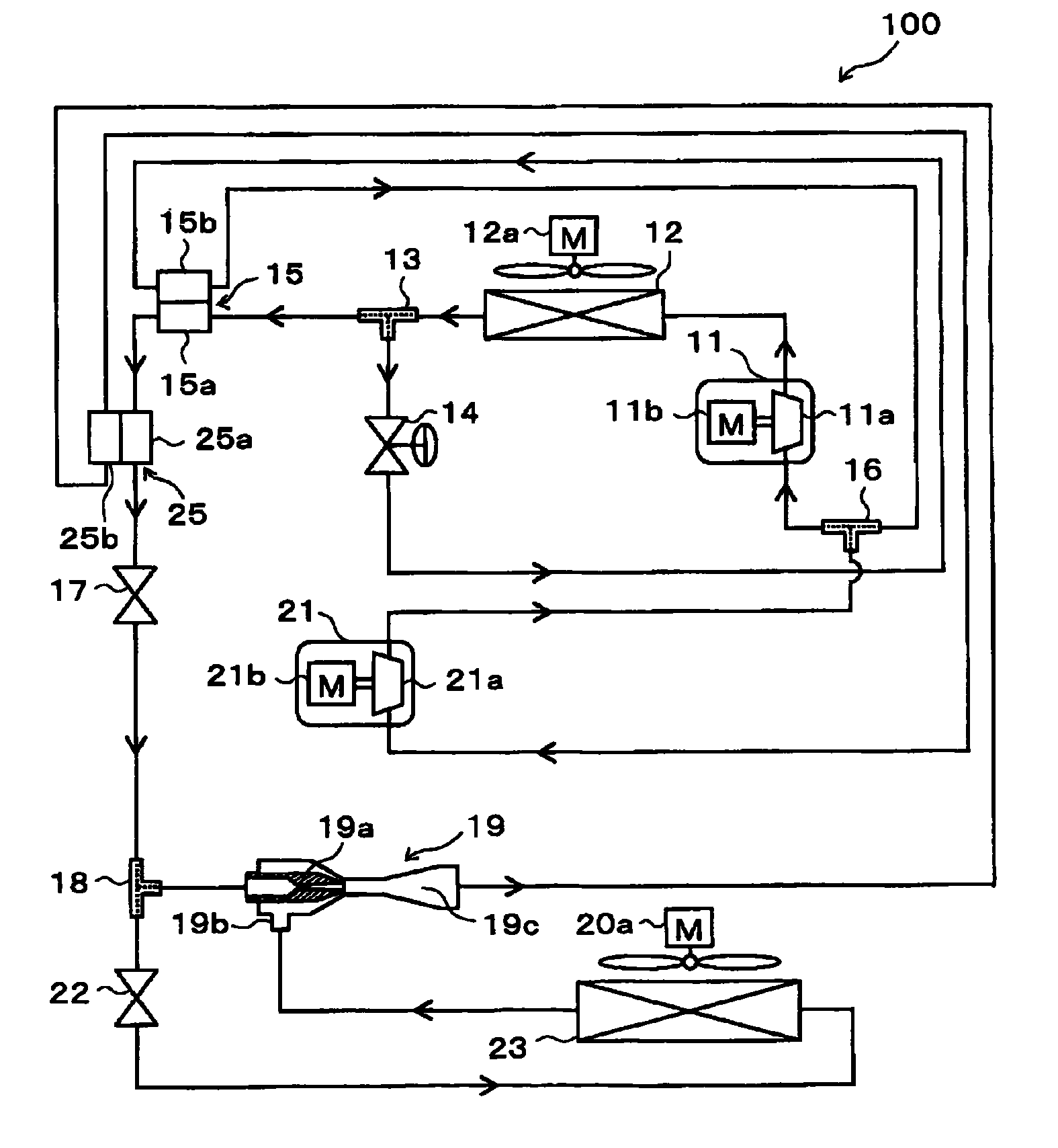
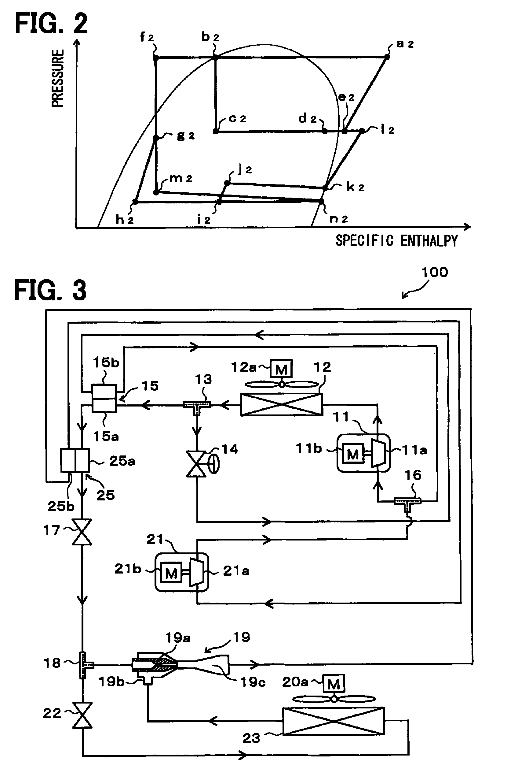
[0378]As shown by the entire schematic diagram of FIG. 3, the present embodiment describes regarding an example in which an auxiliary inner heat exchanger 25 is added and the discharge side evaporator 20 is removed, with respect to the ejector-type refrigerant cycle device 100 of the 1st embodiment. In the example of FIG. 3, the same parts or corresponding parts with the 1st embodiment are indicated by the same reference numbers. The following figures are indicated by the same way.

[0379]The basic structure of the auxiliary inner heat exchanger 25 of the present embodiment is the same as that of the inner heat exchanger 15 of the 1st embodiment. The auxiliary inner heat exchanger 25 is configured to perform heat exchange between the refrigerant passing through a high-pressure side refrigerant passage 25a, having passed through the inner heat exchanger 15 from the first branch portion 13, and the refrigerant passing through a low-pressure side refrigerant passage 25b, ...

3rd embodiment

(3rd Embodiment)

[0386]As shown by the entire schematic diagram of FIG. 5, the present embodiment describes regarding an example in which an auxiliary radiator 24 is added, with respect to the ejector-type refrigerant cycle device 100 of the 1st embodiment. The auxiliary radiator 24 is a heat-radiating heat exchanger in which the high-pressure refrigerant flowing from the first branch portion 13 toward the inner heat exchanger 15 is heat exchanged with air (outside air) outside of the room, blown by the cooling fan 12a, thereby further cooling the high-pressure refrigerant.

[0387]In FIG. 5, the cooling fan 12a is located near the radiator 12 for easily indicating in the figure, however, the cooling fan 12a is configured to blow the outside air to not only the radiator 12 but also to the auxiliary radiator 24. The radiator 12 and the auxiliary radiator 24 may be configured to blow air outside the room of the refrigerator by using respectively independent blower fans.

[0388]The radiator ...

4th embodiment

(4th Embodiment)

[0396]As shown by the entire schematic diagram of FIG. 7, the present embodiment describes regarding an example in which the auxiliary inner heat exchanger 25 similar to the 2nd embodiment is added and the discharge side evaporator 20 is removed, with respect to the ejector-type refrigerant cycle device 100 of the 2nd embodiment.

[0397]In the present embodiment, the refrigerant flowing toward the inner heat exchanger 15 from the first branch portion 13 flows in this order of the auxiliary radiator 24→the inner heat exchanger 15→the auxiliary inner heat exchanger 25→the first fixed throttle 17. The other configurations are the same as those in the 3rd embodiment.

[0398]Operation of the present embodiment with the above structure will be described based on the Mollier diagram of FIG. 8. In the present embodiment, the high-pressure refrigerant flowing out of the radiator 12 is branched in the first branch portion 13 into the flow of the refrigerant flowing toward the ther...


PUM


Abstract

A flow of refrigerant discharged from a first compressor and cooled by a radiator is branched by a first branch portion, and the branched refrigerant of one side is decompressed and expanded by a thermal expansion valve and is heat exchanged with the branched refrigerant of the other side in an inner heat exchanger. Therefore, the branched refrigerant of the other side supplied to the suction side evaporator and a nozzle portion of an ejector can be cooled, thereby improving COP. Furthermore, a suction port of a second compressor is coupled to an outlet side of the ejector so as to secure a drive flow of the ejector, and the refrigerant discharged from the second compressor and the refrigerant downstream of the thermal expansion valve are mixed to be drawn into the first compressor so that an ejector-type refrigerant cycle device can be operated stably.

Description

CROSS REFERENCE TO RELATED APPLICATION[0001]This application is based on Japanese Patent Applications No. 2008-318046 filed on Dec. 15, 2008, and No. 2009-229766 filed on Oct. 1, 2009, the contents of which are incorporated herein by reference in its entirety.FIELD OF THE INVENTION[0002]The present invention relates to an ejector-type refrigerant cycle device including an ejector.BACKGROUND OF THE INVENTION[0003]Conventionally, an ejector-type refrigerant cycle device including an ejector adapted as a refrigerant decompression function and a refrigerant circulation function is known.[0004]For example, in an ejector-type refrigerant cycle device described in Patent Document 1, refrigerant discharged from a compressor is heat-exchanged with outside air in a radiator, and is cooled. The high-pressure refrigerant having been cooled is supplied to a nozzle portion of the ejector, and refrigerant evaporated in a suction side evaporator is drawn from a refrigerant suction port of the eject...

Claims


Application Information

Patent Timeline
Patent Type & Authority Patents(United States)
IPC IPC(8): F25B1/06F25B1/10F25B5/00F25B13/00F25B40/00F25B41/00
CPCF25B41/00F25B40/00F25B1/10F25B2400/13F25B5/00F25B2341/0011F25B13/00
Inventor NISHIJIMA, HARUYUKIYAMADA, ETSUHISANAGANO, YOUHEITANIGUCHI, MASAMI
Owner DENSO CORP
Why Eureka
Try Eureka