Bottle stopper for evacuation pump

Inactive Publication Date: 2014-07-22
HOYT CHASE H +1
View PDF12 Cites 23 Cited by
  • Summary
  • Abstract
  • Description
  • Claims
  • Application Information

AI Technical Summary

Benefits of technology

[0008]One aspect of the invention resides in a stopper with a check valve configured to provide a seal commensurate with the level of vacuum applied to it. The valve is made up of a resilient seat structure (such as made of silicone or rubber) and a plastic plunger with a conical tip designed to mesh perfectly with a seal opening in the seat. The seat structure is dome shaped with the seat opening at the top of the dome and is located at the bottom of the stopper facing up, toward the outside of the bottle. The plunger is slidably contained in a casing above the seat structure so as to engage the seat opening to seal the bottle when the plunger is in its down position and to open the valve when in

Problems solved by technology

The main problem with the stoppers heretofore found in the art is the fact that they lose vacuum rapidly and predictably.
Thus, the preservation effect is gradually re

Method used


Image

  • Bottle stopper for evacuation pump
  • Bottle stopper for evacuation pump
  • Bottle stopper for evacuation pump

Examples


Example

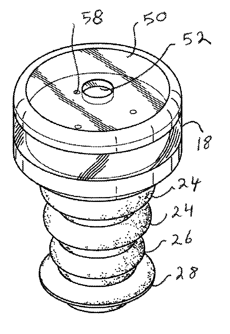
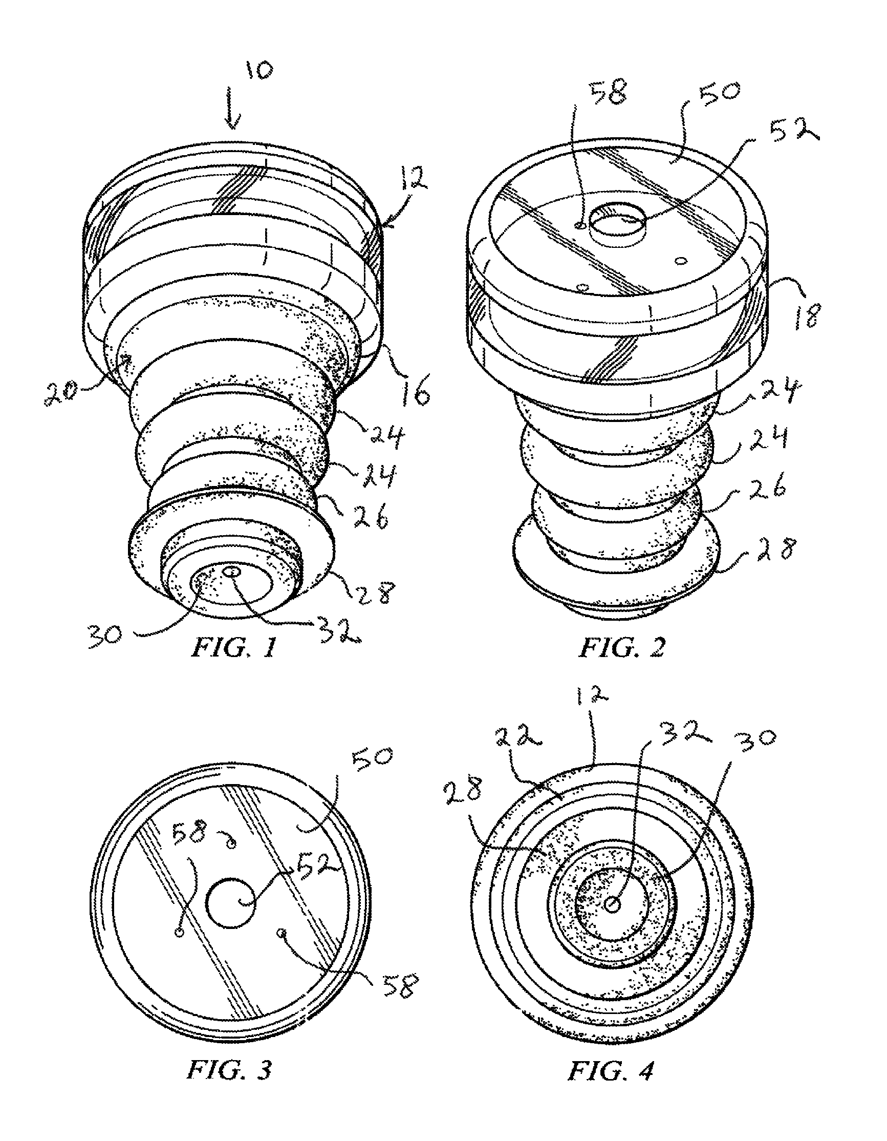
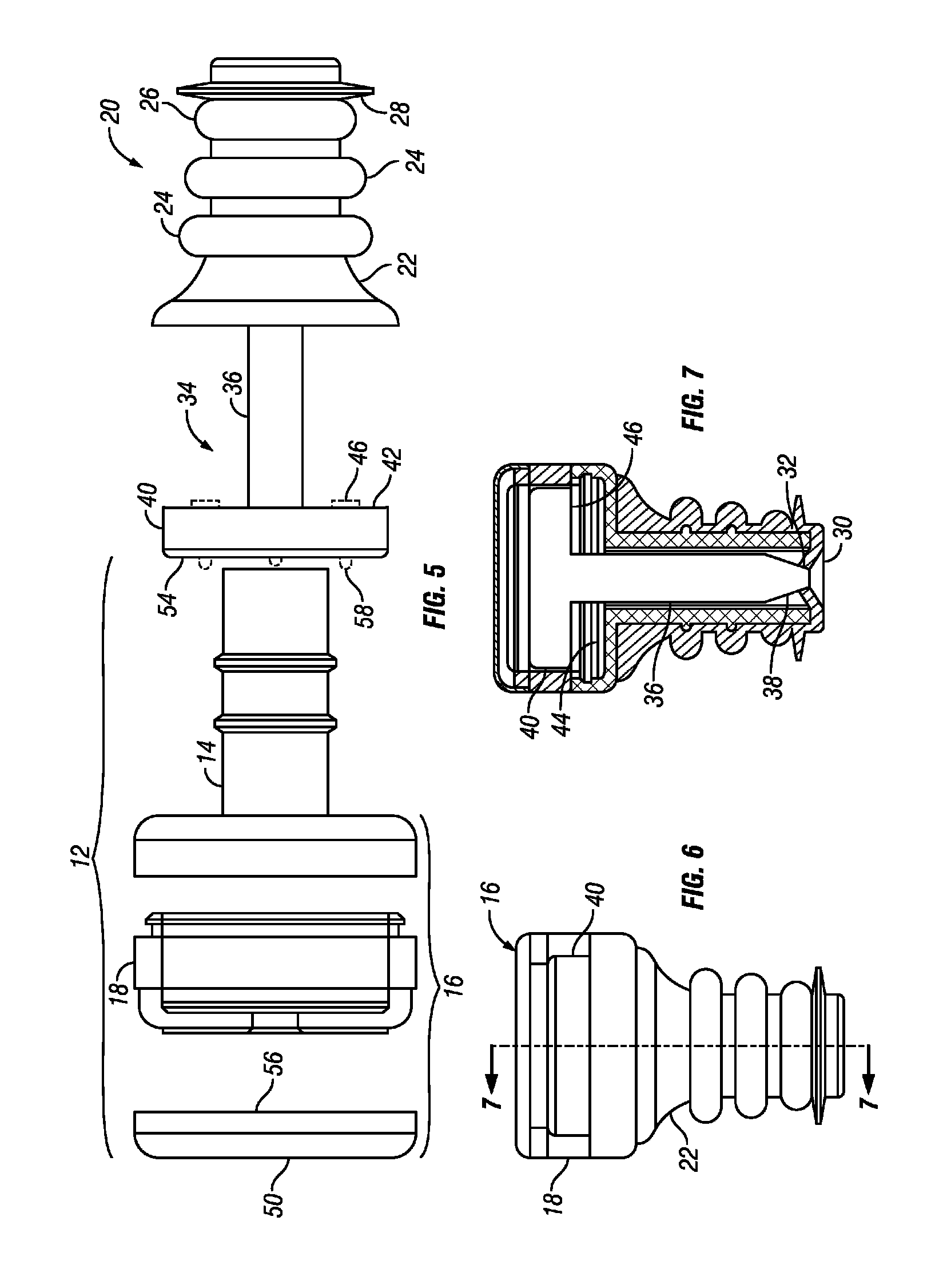
[0023]Referring to FIG. 1, a stopper 10 according to the invention is illustrated in bottom perspective view. As also seen in the top perspective view of FIG. 2 and the exploded view of FIG. 5, the stopper 10 is the combination of several separate components. A hollow casing 12 provides the structure around which the stopper is formed and consists of a lower tubular section 14 (seen in the exploded view of FIG. 5) and an upper, larger, cylindrical section 16. The casing is preferably made of plastic and the outer wall 18 of the cylindrical portion 16 is preferably transparent. A silicone sleeve 20 is mounted on the lower tubular section 14 and provides the structure that seals the stopper to the inner wall of the neck of the bottle being evacuated for preservation of its contents. To that end, the sleeve 20 has a main core structure 22 (see also FIG. 6) of generally frusto-conical geometry for insertion into the neck of the bottle and several ribs that provide the seal. As seen in t...


PUM


Abstract

A stopper includes a hollow casing with a resilient, ribbed sleeve that forms a valve seat. An interior plunger has a tip configured to mesh with the valve seat when in its down position and to open the valve when in its up position. An upper flange in the plunger provides an additional seal and is visible through a transparent wall in the casing. A vacuum in the bottle draws the plunger downward increasing the pressure with which the plunger presses against the seat, thus securing a long-lasting seal that maintains the vacuum in the bottle. When the vacuum is released, the resilience of the seat structure pushes the plunger upward, rendering it visible as an indicator of vacuum through the transparent wall. An opening in the casing allows connection to a pump to create the vacuum in the bottle.

Description

RELATED APPLICATIONS[0001]This application is based on and claims the priority of provisional application Ser. No. 61 / 608,775 filed Mar. 9, 2012, hereby incorporated by reference.BACKGROUND OF THE INVENTION[0002]1. Field of the Invention[0003]The invention relates to bottle stoppers for maintaining vacuum in a bottle, especially a wine bottle, after de-corking and partial evacuation of air from the bottle.[0004]2. Description of the Prior Art[0005]Wine bottles are normally sealed with corks or caps that are removed to gain access to the wine and then put back on the bottle if the wine is not completely consumed. In order to preserve the freshness of left-over wine that is retained for future consumption, it has become accepted practice to create a vacuum after the cork is put back on the bottle. This condition is believed to prolong the shelf life of an open bottle of wine by minimizing the effect of oxygen on the wine left over in the bottle.[0006]To that end, various pumps and rel...

Claims


Application Information

Patent Timeline
IPC IPC(8): B65D51/16B65D39/14B65D39/04
CPCB65D51/1661B65D39/12B65D81/2038B65D79/005
Inventor HOYT, CHASE H.HOYT, ROBERT Q.
Owner HOYT CHASE H
Why Eureka
Try Eureka