Food cooking container provided with a thermal indicator

a technology for cooking containers and indicators, applied in the field of containers, can solve the problems of loss of effectiveness, difficulty in adjusting the temperature of food containers, and the drawback of special handles for indicator devices, etc., and achieve the effect of convenient fitting into the handle, convenient disassembly and assembly, and convenient formation

Active Publication Date: 2014-07-22
BALLARINI PAOLO E FILI SPA
View PDF16 Cites 76 Cited by
  • Summary
  • Abstract
  • Description
  • Claims
  • Application Information

AI Technical Summary

Benefits of technology

[0017]With a device of this type, an aperture can be provided in cooking container handles or handgrips, which can be easily formed in a manner totally independent of the handle shape. The sensor of the electronic device is inserted into this aperture and is brought into contact with a hot part of the cooking container at one end and with a metal dissipation mass constituting the cold part at the other end, hence enabling the temperature gradient of the hot pan / cold mass system to be utilized.
[0020]In the most simple solution, the electronic device can be conveniently formed without a microcontroller and possibly without energy storage elements.
[0021]In a convenient solution, particularly in relation to withstanding dishwasher action, the thermal indicator device can be made removable, and the removed device be used freely in combination with other cooking containers, provided with a similar conveniently disposed seat.
[0022]A further advantage of the device is that it can be easily fitted into a handle, because having no battery it only requires a waterproofing protection, which is simple to make.

Problems solved by technology

Known temperature indicator systems in food cooking containers have the drawback that if thermochromatic pigments are applied, these lose effectiveness over time due to repeated vessel cleaning.
Battery powered devices have problems relating to device safety, because of evident battery explosion danger when exposed to the heat of the vessel, with consequent food contamination, in addition to maintenance and disposal costs.
Other recently known temperature indicator devices have the drawback of requiring handles of special size and shape containing seats shaped to match the shape of the indicator device.
This fact requires the formation of suitable moulds for handle manufacture, hence increasing the final product cost.
Moreover, this permanent incorporation of temperature indicator devices, in particular those battery powered, can generate problems of impermeabilization or heat resistance when, for example, the cooking vessel is cleaned in a dishwasher.
A further limit of devices pertaining to the prior art is the fact that for each cooking vessel, for example a frying pan, a saucepan or another container, an indicator device has to be permanently mounted in the handle of each individual container, a fact which substantially increases the vessel cost.

Method used


Image

  • Food cooking container provided with a thermal indicator
  • Food cooking container provided with a thermal indicator
  • Food cooking container provided with a thermal indicator

Examples


Embodiment Construction

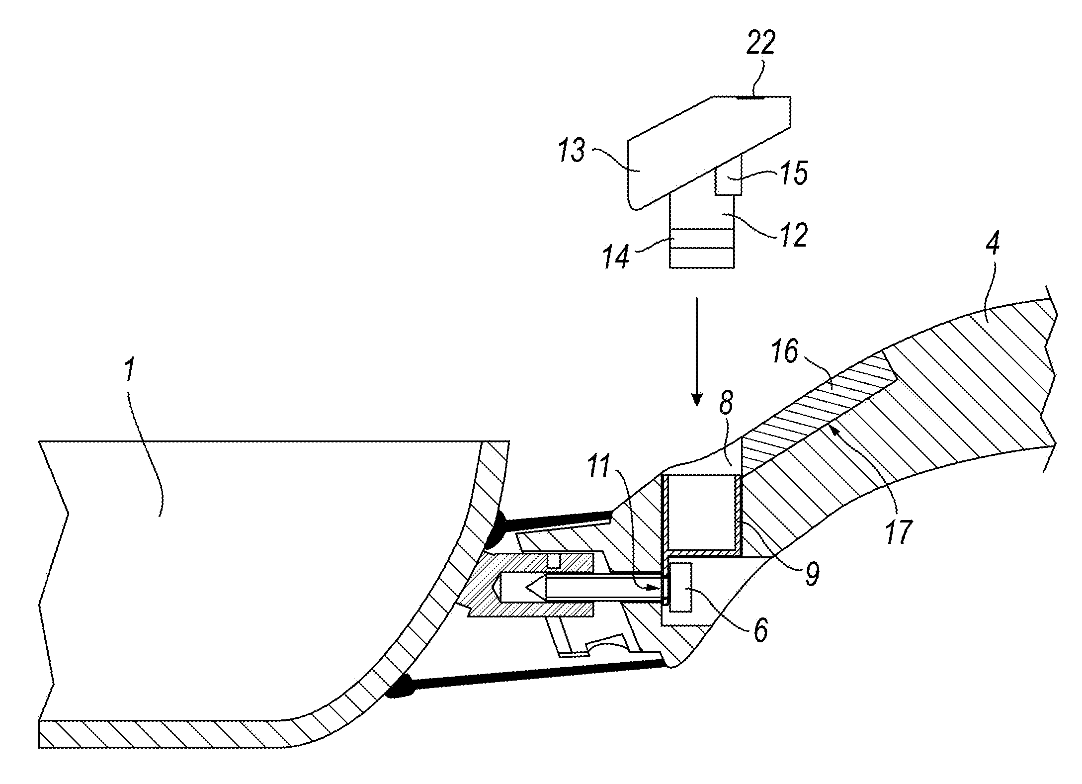
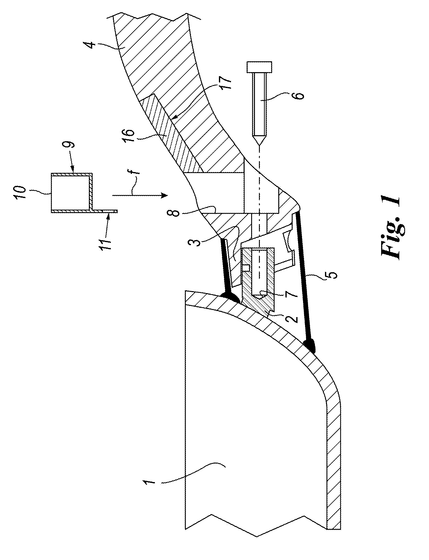
[0029]As can be seen from FIG. 1, the food cooking container, for example a frying pan 1, presents a projecting fixing shank 2 forming a seat for the end 3 of a handle 4.

[0030]The end 3 is surrounded by a tubular piece 5 which is rigid with the body of the pan 1.

[0031]The handle 4 is locked in known manner with the aid of a screw 6 screwed into the threaded seat 7 of the shank 2.

[0032]The handle 4 presents an upwardly open seat 8 into which, as indicated by the arrow (f), a cup-shaped sheath 9 of metal construction presenting upperly an aperture 10 and lowerly a prolongation 11 can be inserted.

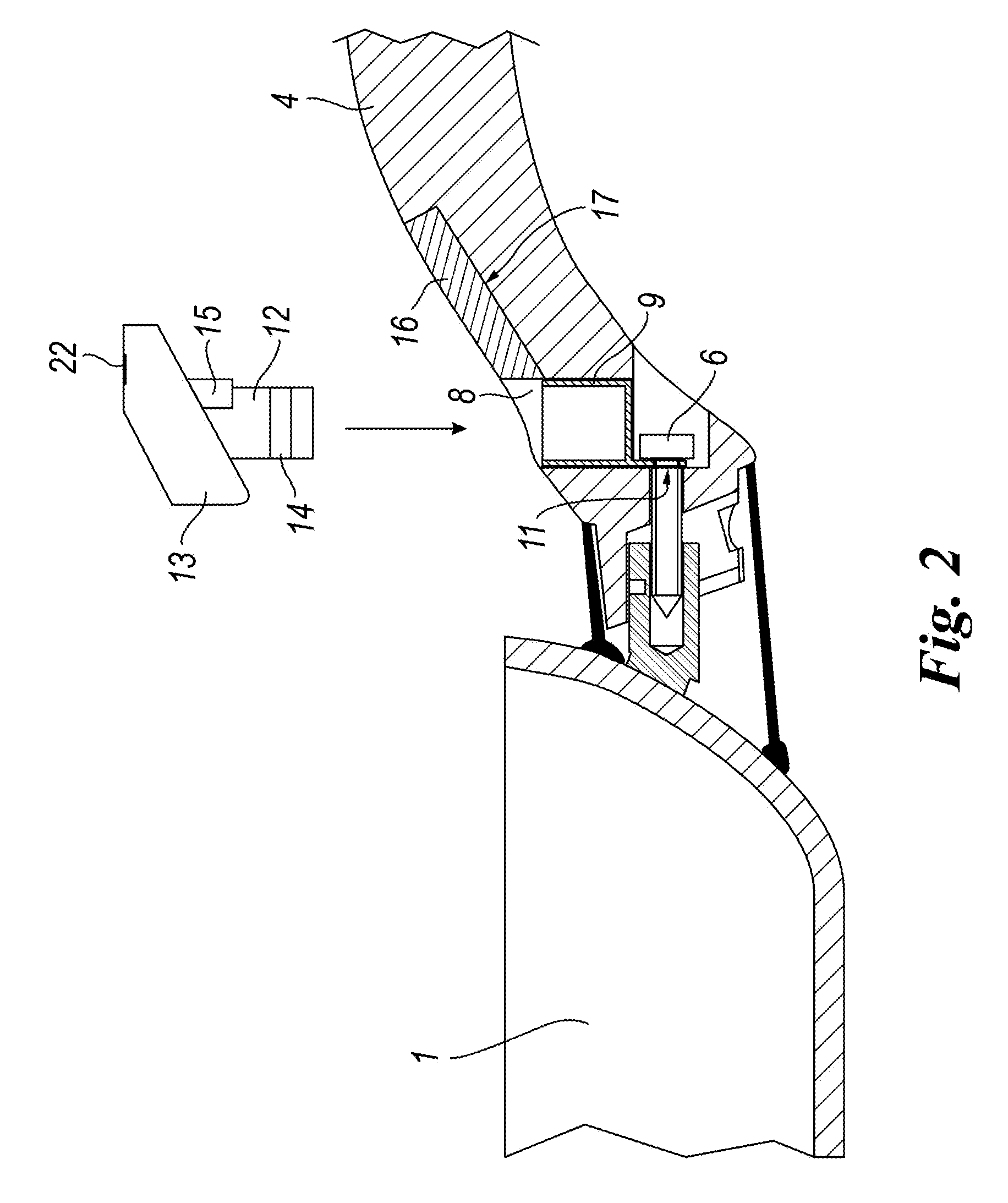
[0033]From FIG. 2 it can be seen that the metal sheath 9 is inserted into the seat 8 of the handle 4 and the prolongation 11 of the sheath 9 is traversed by the fixing screw 6, this screw also acting as a means for transmitting the heat originating from the body of the pan 1. In practice, said prolongation 11 forms the hot terminal of the device.

[0034]From FIG. 2 it can be seen that above the ...


PUM

PropertyMeasurementUnit
temperatureaaaaaaaaaa
thermal energyaaaaaaaaaa
energyaaaaaaaaaa

Abstract

A food cooking container provided with an electronic temperature monitoring device, the electronic temperature monitoring device being powered by converting thermal energy into electrical energy by the parasitic exploitation of temperature differences generated between the hot container and a heat dissipating metal mass, and activates a device in the form of a piezoelectric buzzer or LEDs, to indicate pre-set safety temperature limits. The electronic temperature monitoring device includes an electronic thermoelectric harvesting sensor for converting thermal energy into electrical energy via its electronic thermoelectric harvesting system.

Description

CROSS-REFERENCE TO RELATED APPLICATIONS[0001]This application claims priority under 35 USC 119 from Italian Patent Application No. MI2011A002356, filed on Dec. 22, 2011, incorporated herein by reference.FIELD OF THE INVENTION[0002]The invention relates to a container, used for food cooking, for which container a utilization safety condition is to be achieved.[0003]It is well known that a cooking means can be forgotten on the heat source and that such an event could cause excessive heating, with the danger of fire and damage during food cooking, and damage to the vessel itself.BACKGROUND OF THE INVENTION[0004]Usually, commercially available utensils used for food cooking present different devices used as temperature indicators.[0005]These indicators are incorporated into the container handles and are intended to provide information regarding the cooking temperature attained or a temperature relating to utensil handling safety on termination of cooking.[0006]Known temperature indicato...

Claims


Application Information

Patent Timeline
Patent Type & Authority Patents(United States)
IPC IPC(8): A47J45/06A47J43/00G01K1/00G01K13/00
CPCA47J45/068A47J2202/00
Inventor FERRON, FRANCESCOFERRON, JACOPO
Owner BALLARINI PAOLO E FILI SPA
Why Eureka
Try Eureka