Automatic transmission for hybrid vehicle

a hybrid vehicle and automatic transmission technology, applied in the direction of fluid couplings, gearings, couplings, etc., can solve the problems of large amount of oil flowing into the oil cooler, unfavorable control of the hydraulic servo, and inability to provide an oil cooler at such a location, so as to achieve accurate preparation for the engagement of the friction engagement element

Active Publication Date: 2014-07-22
AISIN AW CO LTD
View PDF12 Cites 14 Cited by
  • Summary
  • Abstract
  • Description
  • Claims
  • Application Information

AI Technical Summary

Benefits of technology

[0008]It is therefore an object of the present invention to provide a hybrid vehicle automatic transmission that enables a reduction in size of an electric oil pump and hence a cost reduction while a stable hydraulic pressure supplied by the electric oil pump during EV travel is secured.
[0018]In this configuration, the second reverse flow prevention mechanism is interposed between the first hydraulic pressure supply source and the second hydraulic pressure supply source to prevent reverse flow of a hydraulic pressure from the first hydraulic pressure supply source to the second hydraulic pressure supply source, and the third reverse flow prevention mechanism is provided on the third oil passage on the second hydraulic pressure supply source side with respect to the merging point to prevent reverse flow of a hydraulic pressure from the first hydraulic pressure supply source to the second hydraulic pressure supply source. Thus, it is possible to prevent reverse flow of a hydraulic pressure to the second hydraulic pressure supply source during travel with the first hydraulic pressure supply source producing a hydraulic pressure. In particular, reverse flow of a hydraulic pressure from the oil cooler to the second hydraulic pressure supply source via the third oil passage is not caused, which prevents an insufficient amount of oil for the portion to be lubricated.

Problems solved by technology

Therefore, providing the oil cooler at a location from which a hydraulic pressure is supplied to a hydraulic servo for a friction engagement element (such as a clutch or a brake) would result in unfavorable control of the hydraulic servo.
Thus, the oil cooler may not be provided at such a location.
Thus, the oil cooler is inevitably provided between the regulator valve and the lubrication circuit.
However, when the oil cooler is disposed in the oil passage between the regulator valve and the lubricating oil passage to supply a lubricating pressure directly from the electric oil pump to the lubricating oil passage, a large amount of oil flows into the oil cooler.
Thus, it is difficult to secure a stable hydraulic pressure (that does not fall below a predetermined value) to be supplied to the hydraulic servo for the friction engagement element (hydraulic pressure to be supplied to the regulator valve) during EV travel.
In order to secure a stable hydraulic pressure to be supplied to the hydraulic servo, it is necessary to increase the size of the electric oil pump to produce a sufficient hydraulic pressure, which hinders a reduction in cost of the hybrid vehicle automatic transmission.

Method used


Image

  • Automatic transmission for hybrid vehicle
  • Automatic transmission for hybrid vehicle
  • Automatic transmission for hybrid vehicle

Examples


Embodiment Construction

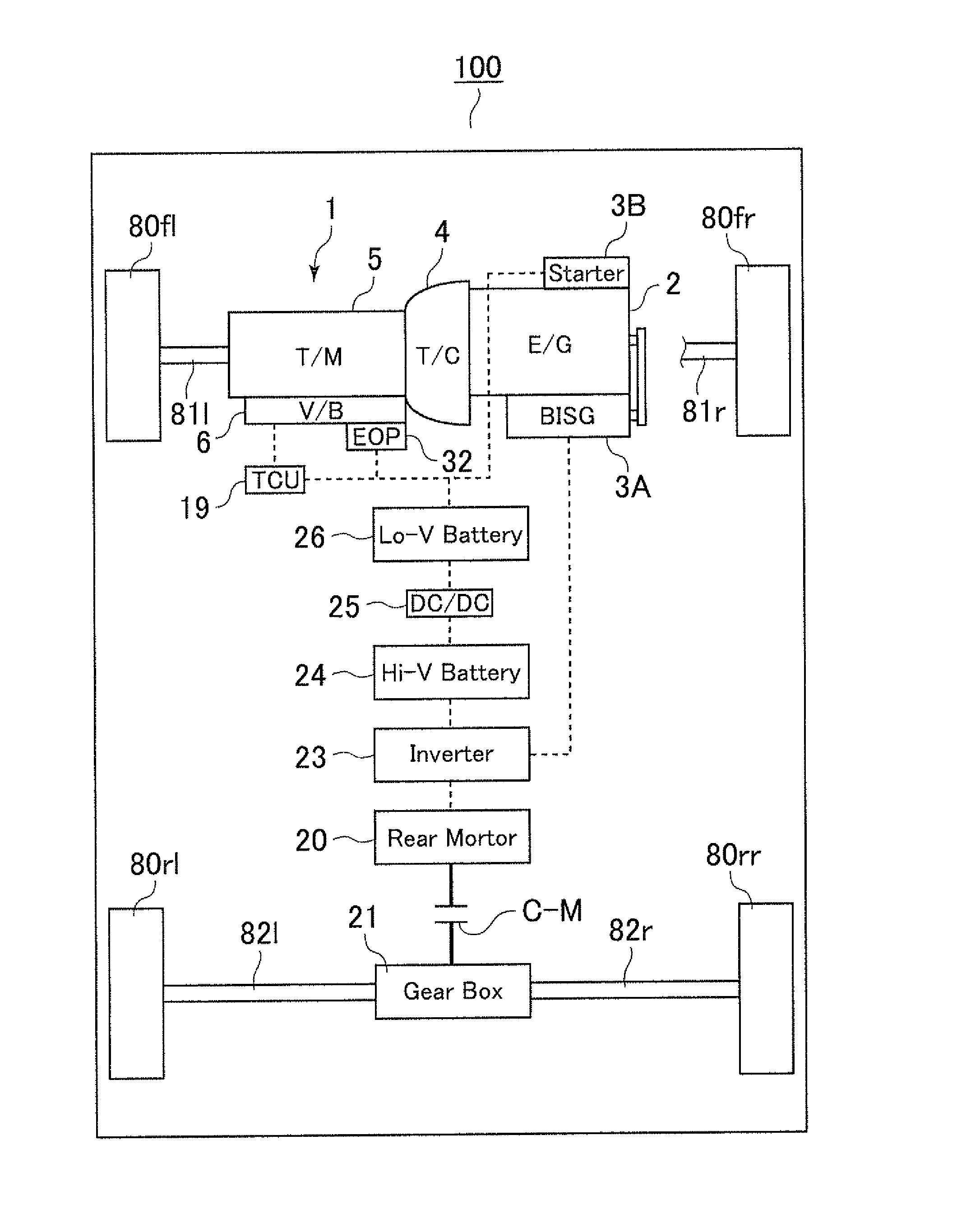
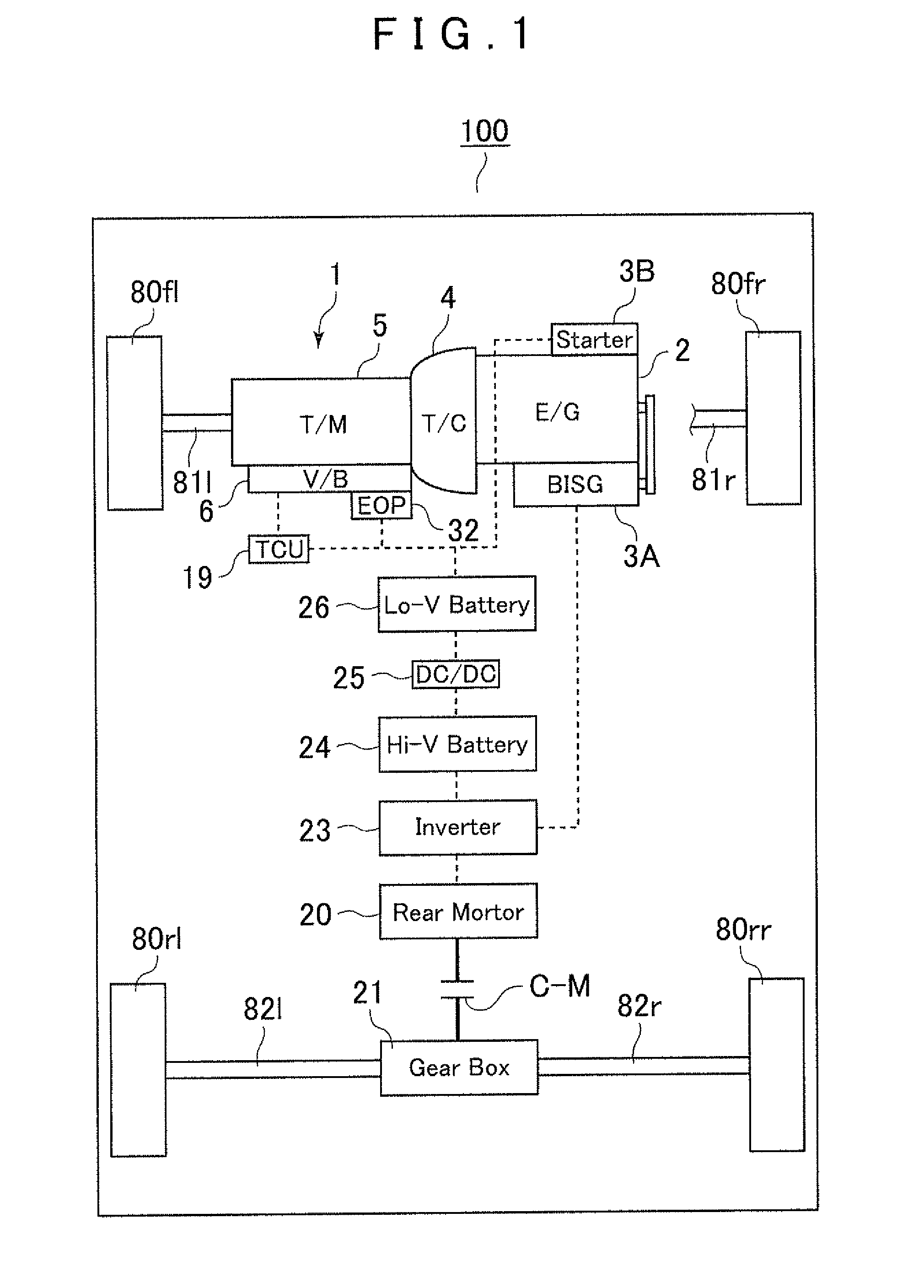
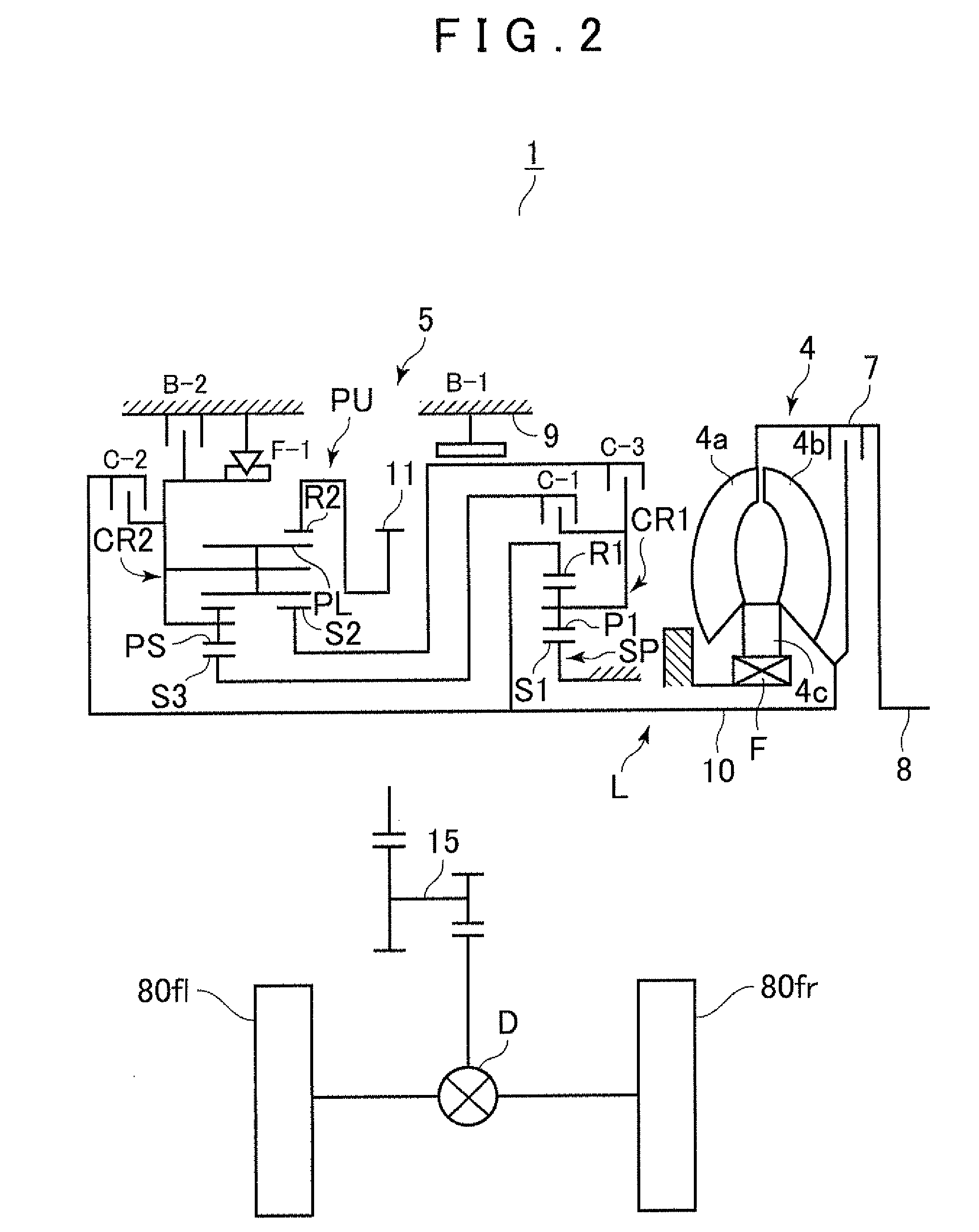
[0023]An embodiment of the present invention will be described below with reference to FIGS. 1 to 4. First, an example of a hybrid vehicle to which the present invention may be applied will be described with reference to FIG. 1.

[0024]As shown in FIG. 1, a hybrid vehicle 100 according to the embodiment is a rear-motor hybrid vehicle, which is formed like a so-called FF (front-engine front-drive) vehicle including an internal combustion engine (E / G) 2 mounted in the front side of the vehicle and a hybrid vehicle automatic transmission (hereinafter simply referred to as “automatic transmission”) 1 mounted on a transfer path L (see FIG. 2) between the internal combustion engine 2 and left and right front wheels 80fl, 80fr, and which also includes a rear motor (rotary electric machine) 20 drivably coupled to left and right rear wheels 80rl, 80rr. That is, the hybrid vehicle 100 is configured to be able to be driven by the front wheels during engine travel, driven by the rear wheels durin...


PUM


Abstract

An automatic transmission for a hybrid vehicle comprising a first hydraulic pressure supply source driven with an internal combustion engine; a second hydraulic pressure supply source driven independently of the first supply source; and a regulator valve regulating hydraulic pressure produced by the supply sources. A first oil passage supplying line pressure regulated by the regulator valve to a hydraulic servo operating a friction engagement element; a second oil passage supplying hydraulic pressure discharged from the regulator valve to a lubricated portion via an oil cooler; and a thud oil passage merged with the second oil passage at a point downstream of the oil cooler supplying the hydraulic pressure of the second supply source to the lubricated portion. A first reverse flow prevention mechanism is disposed between the oil cooler and the merging point to prevent reverse flow of hydraulic pressure.

Description

INCORPORATION BY REFERENCE[0001]The disclosure of Japanese Patent Application No. 2012-044746 filed on Feb. 29, 2012 including the specification, drawings and abstract is incorporated herein by reference in its entirety.BACKGROUND OF THE INVENTION[0002]The present invention relates to an automatic transmission to be mounted on a hybrid vehicle, for example, and in particular to a hybrid vehicle automatic transmission controlled so that the hybrid vehicle automatic transmission is able to run idle in the case where a vehicle is driven by a rotary electric machine,DESCRIPTION OF THE RELATED ART[0003]In recent years, a variety of hybrid vehicles have been developed to improve the fuel efficiency of the vehicles, for example. Some of such hybrid vehicles include an automatic transmission that changes the speed of rotation of an internal combustion engine during hybrid travel and engine travel. In the hybrid vehicle including the automatic transmission, at least a part of the automatic t...

Claims


Application Information

Patent Timeline
Patent Type & Authority Patents(United States)
IPC IPC(8): F16H3/72F16H57/04
CPCY02T10/6221F16H57/0435F16H61/0206F15B21/001F16H61/0031F16H2061/0037
Inventor MOTODOHI, KAZUHIKOIGA, SHINICHIROMURANAKA, YASUNARI
Owner AISIN AW CO LTD
Why Eureka
Try Eureka