Radiation imaging device, radiation imaging system, and method for affixing radiation conversion panel in radiation imaging device

a radiation imaging and radiation imaging technology, applied in the direction of radiation controlled devices, optical radiation measurement, instruments, etc., can solve the problems of radiation conversion panel cracking or peeling, assembly cracking or peeling, plastic tends to be deformed under environmental conditions, etc., to maintain the planarity of radiation conversion panel, and prevent cracking or peeling

Inactive Publication Date: 2014-08-05
FUJIFILM CORP
View PDF22 Cites 2 Cited by
  • Summary
  • Abstract
  • Description
  • Claims
  • Application Information

AI Technical Summary

Benefits of technology

[0105]According to the first invention, as described above, the external force applying mechanism applies an external force to the peripheral edge of the radiation conversion panel in order to prevent the peripheral edge from becoming deformed, i.e., warped, depending on at least one of a temperature change and a humidity change, i.e., a change in environmental conditions, thereby keeping the radiation conversion panel flat. According to the first invention, therefore, the radiation conversion panel is kept flat, i.e., planarity of the radiation conversion panel is maintained, in view of changes in environmental conditions.
[0106]According to the first invention, since the radiation conversion panel is not bonded to other members, but rather an external force is applied to the peripheral edge of the radiation conversion panel in order to keep the radiation conversion panel flat, the radiation conversion panel is prevented from becoming deformed and hence from cracking or peeling.
[0107]According to the second invention, the radiation conversion panel and the external force applying mechanism are stacked together in integral combination. If the radiation conversion panel becomes deformed due to a change in environmental conditions, the radiation conversion panel and the external force applying mechanism are deformed integrally together. According to the second invention, while the radiation conversion panel and the external force applying mechanism are allowed to deform, the external force applying mechanism applies an external force depending on the environmental conditions in order to change the radiation conversion panel, thereby keeping the radiation conversion panel flat, i.e., to maintain planarity of the radiation conversion panel. As a consequence, the second invention is more effective in preventing cracking and peeling of the radiation conversion panel due to deformation thereof than if other members were simply bonded to the radiation conversion panel according to the technology disclosed in Japanese Patent No. 2706725.
[0108]According to the third invention, the external force applying mechanism is used to press the radiation conversion panel against the inner wall surface of the panel housing unit, thereby holding components in the radiation conversion panel closely together in a natural configuration, and also easily and securely positioning the radiation conversion panel. According to the third invention, therefore, the components in the radiation conversion panel can be held closely together by a simple structure. Since the radiation conversion panel is securely positioned by pressing the components thereof, the components do not need to be bonded by an adhesive. Thus, the radiation conversion panel is prevented from cracking or peeling, and can easily be replaced for enabling increased maintainability.
[0033]According to the present invention, furthermore, the external force applying mechanism is used to press the radiation conversion panel against the inner wall surface of the panel housing unit, thereby holding components in the radiation conversion panel closely together in a natural configuration, and also easily and securely positioning the radiation conversion panel. According to the present invention, therefore, the components in the radiation conversion panel are held closely together by a simple structure. Since the radiation conversion panel is securely positioned by pressing the components thereof, the components do not need to be bonded by an adhesive. Accordingly, the radiation conversion panel is prevented from cracking or peeling, and the radiation conversion panel can easily be replaced for providing increased maintainability.

Problems solved by technology

However, since plastic has a greater coefficient of thermal expansion than glass, plastic tends to be deformed under environmental conditions, e.g., temperature, humidity, etc., of the radiation conversion panel.
According to the technology disclosed in Japanese Patent No. 2706725, since the thermal strain corrector and the board, which have widely different coefficients of thermal expansion, are bonded to each other, the interface therebetween is stressed due to repeated temperature changes, which tends to cause the assembly to crack or peel.
More specifically, since the thermal strain corrector simply is bonded in a planar form to the radiation conversion panel, in a case where the radiation conversion panel is deformed due to temperature changes, the radiation conversion panel is likely to crack or peel.
It is difficult to prevent the radiation conversion panel from being deformed due to temperature changes.
Since plastic has a greater coefficient of thermal expansion than glass and tends to be deformed under environmental conditions, e.g., temperature, humidity, etc., of the radiation conversion panel, plastic fails to provide sufficient adhesion between the photoelectric transducer layer and the scintillator of the radiation conversion panel.
However, adhesive bonding is problematic in that due to the different coefficients of thermal expansion of various components used in the radiation conversion panel, the bonded surfaces (interfaces) are stressed due to repeated temperature changes, which also tends to bring about cracking or peeling in the radiation conversion panel.
Depressurization of the cassette requires an evacuating system including a vacuum pump and other parts, resulting in increased system size and cost.
If the panel housing unit is made of CFRP (Carbon-Fiber-Reinforced Plastics) or the like to provide better load resistance and reduced weight, then if the radiation conversion panel is taken into and out of the panel housing unit while the radiation conversion panel is held in contact with the inner wall surface of the panel housing unit, some of the carbon fibers that constitute the CFRP may become broken and frayed, which tends to degrade the quality of the captured radiographic image.
Furthermore, if the radiation conversion panel is taken into and out of the panel housing unit while the radiation conversion panel is held in contact with the inner wall surface of the panel housing unit, the surface of the radiation conversion panel, e.g., the surface of the scintillator, is likely to become damaged.
In the case where the surface of the radiation conversion panel is damaged, the quality of the captured radiographic image is degraded, and control lines for supplying control signals to read the radiographic image, as well as signal lines for outputting signals representative of the radiographic image to an external circuit, are likely to be cut off.

Method used


Image

  • Radiation imaging device, radiation imaging system, and method for affixing radiation conversion panel in radiation imaging device
  • Radiation imaging device, radiation imaging system, and method for affixing radiation conversion panel in radiation imaging device
  • Radiation imaging device, radiation imaging system, and method for affixing radiation conversion panel in radiation imaging device

Examples


first embodiment

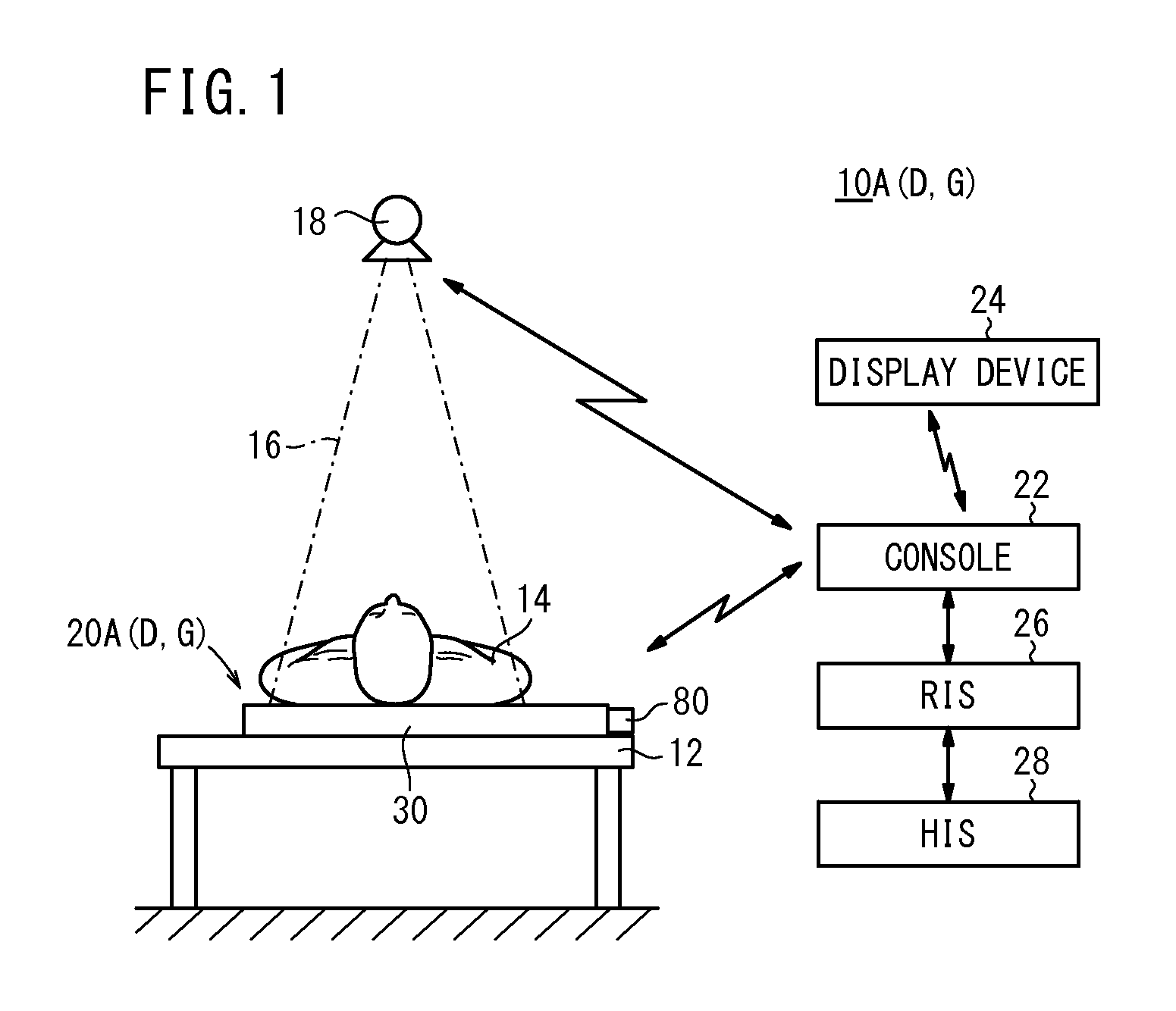
[0112]FIG. 1 is a schematic view of a radiographic image capturing system incorporating a cassette according to the present invention;

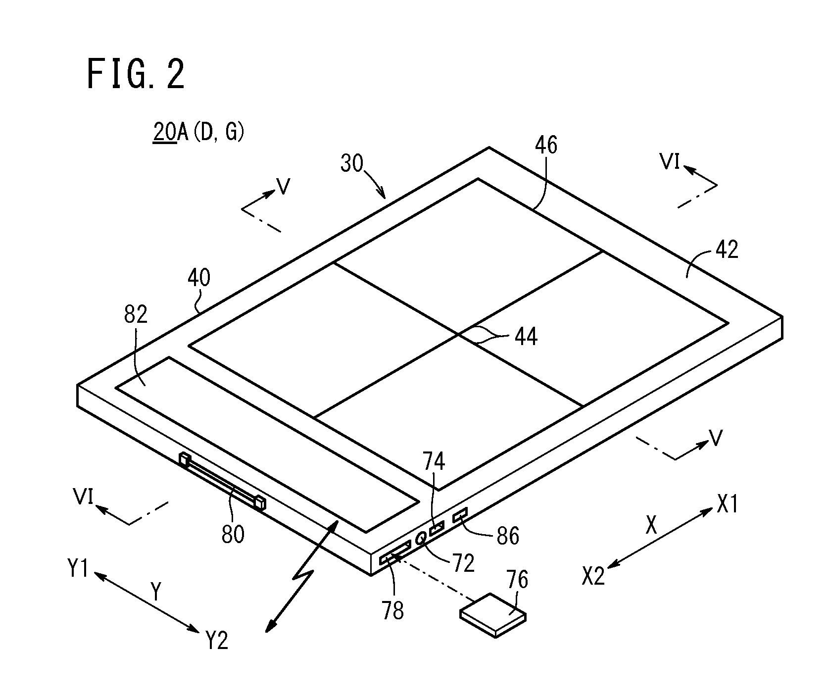
[0113]FIG. 2 is a perspective view of the cassette shown in FIG. 1;

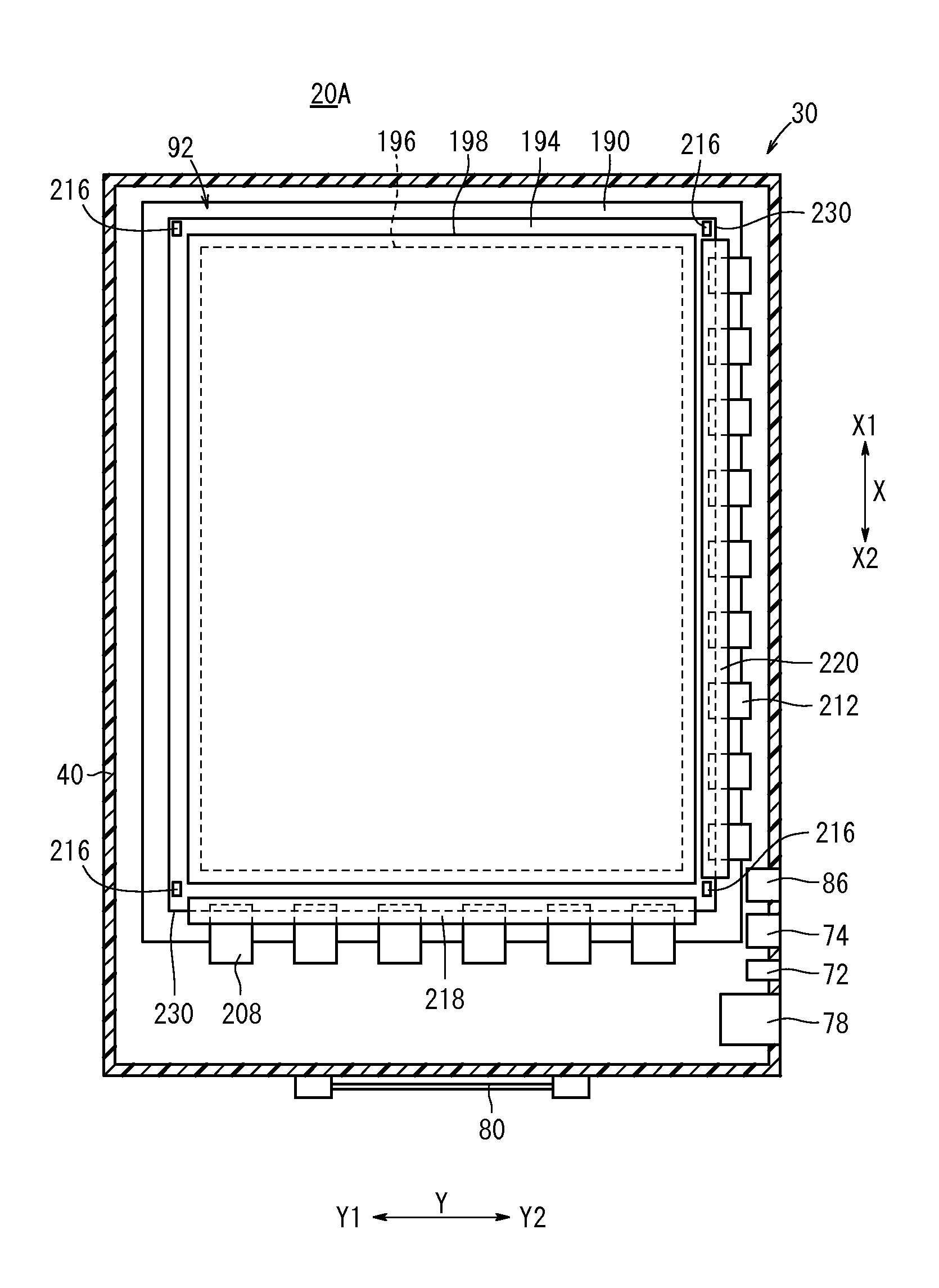
[0114]FIG. 3 is a plan view of the cassette shown in FIG. 1, with an upper wall thereof cut away;

[0115]FIG. 4 is a plan view, partially cut away, of the cassette shown in FIG. 1;

[0116]FIG. 5 is a cross-sectional view taken along line V-V of FIG. 2;

[0117]FIG. 6 is a cross-sectional view taken along line VI-VI of FIG. 2;

[0118]FIG. 7A is a view schematically showing the shape of a radiation conversion panel during a rise in temperature thereof;

[0119]FIG. 7B is a view schematically showing the shape of the radiation conversion panel during a temperature drop thereof;

[0120]FIG. 8A is a view schematically showing the position of an external force applying unit with respect to the radiation conversion panel;

[0121]FIG. 8B is a view schematically showing the manner in which the external force a...

second embodiment

[0134]FIG. 21 is a schematic view of a radiographic image capturing system incorporating a cassette according to the present invention;

[0135]FIG. 22 is a block diagram of the cassette shown in FIG. 21;

[0136]FIG. 23A is a perspective view showing the cassette in a state in which the cassette is carried;

[0137]FIG. 23B is a perspective view showing the cassette in a state in which the cassette captures a radiographic image;

[0138]FIG. 24 is a fragmentary perspective view showing the position of a flexible board on a hinge shown in FIGS. 21, 23A, and 23B;

[0139]FIG. 25 is a cross-sectional view taken along line XXV-XXV of FIG. 23B;

[0140]FIG. 26 is a cross-sectional view taken along line XXVI-XXVI of FIG. 23B;

[0141]FIG. 27 is a cross-sectional view taken along line XXVII-XXVII of FIG. 23B;

[0142]FIG. 28 is a cross-sectional view taken along line XXVIII-XXVIII of FIG. 23B;

third embodiment

[0143]FIG. 29 is a schematic view of a radiographic image capturing system incorporating a cassette according to the present invention;

[0144]FIG. 30 is a perspective view of the cassette shown in FIG. 29;

[0145]FIG. 31 is a cross-sectional view taken along line XXXI-XXXI of FIG. 30;

[0146]FIG. 32 is a cross-sectional view taken along line XXXII-XXXII of FIG. 30;

[0147]FIG. 33 is a cross-sectional view of a cassette according to a fifth modification;

[0148]FIG. 34 is a cross-sectional view of the cassette according to the fifth modification;

[0149]FIG. 35 is a cross-sectional view of a cassette according to a sixth modification;

[0150]FIG. 36 is a cross-sectional view of the cassette according to the sixth modification;


PUM


Abstract

Disclosed is a radiation imaging device configuring a radiation imaging system. Specifically disclosed is a radiation imaging device wherein external force action mechanisms are capable of applying external force to the peripheral sections of a radiation conversion panel, or applying the external force while being laminated on the radiation conversion panel, or pressing the radiation conversion panel against the inner wall of a panel containing unit, which contains the radiation conversion panel, at least in imaging when radiation is applied.

Description

CROSS-REFERENCE TO RELATED APPLICATIONS AND PRIORITY CLAIMS[0001]This application is a Continuation of International Application No. PCT / JP2011 / 060101 filed on Apr. 26, 2011, which was published under PCT Article 21(2) in Japanese, which is based upon and claims the benefit of priority from Japanese Patent Applications No. 2010-105855 filed on Apr. 30, 2010, No. 2010-105858 filed on Apr. 30, 2010, No. 2010-105862 filed on Apr. 30, 2010, and No. 2010-119553 filed on May 25, 2010, the contents all of which are incorporated herein by reference.TECHNICAL FIELD[0002]The present invention relates to a radiographic image capturing apparatus (radiation imaging device) having a radiation conversion panel for converting radiation into a radiographic image, a radiographic image capturing system (radiation imaging system) having a radiographic image capturing apparatus and a control device for controlling the radiographic image capturing apparatus, and a method of securing (affixing) a radiatio...

Claims


Application Information

Patent Timeline
Patent Type & Authority Patents(United States)
IPC IPC(8): G01J1/00G01T1/24G01T1/29
CPCG01T1/20A61B6/4283A61B6/4423A61B6/4488A61B6/54A61B6/563G03B42/04
Inventor NAKATSUGAWA, HARUYASUNISHINO, NAOYUKIOHTA, YASUNORIIWAKIRI, NAOTO
Owner FUJIFILM CORP
Why Eureka
Try Eureka