
Land grid array semiconductor device packages

a technology of semiconductor devices and capillaries, applied in semiconductor devices, semiconductor/solid-state device testing/measurement, semiconductor/solid-state device details, etc., can solve the problems of difficult, if not impossible in some circumstances, to place the inner end of the lead finger of the lead frame in close proximity to the bond pad, and the capillary head of the wire bonding capillary head cannot be accurately placed to avoid contact with the adjacent bond pad, so as to facilitate the connection of other components or wire bond

Active Publication Date: 2014-08-05
MICRON TECH INC
View PDF27 Cites 2 Cited by
  • Summary
  • Abstract
  • Description
  • Claims
  • Application Information

AI Technical Summary

Benefits of technology

[0010]The latter, two-dimensional pad array may also be employed in accordance with the present invention, for connection of one or more active components, one or more passive components, or both types of components, to the land grid array package. In addition, pads of the two-dimensional pad array may be employed in a repair function, to connect pads by wire bonding to lead fingers of a lead frame in case there are open, or shorted power, ground, bias or signal paths in the interposer. Further, some or all of the two-dimensional array of pads may be connected to different terminal pads than those to which the lands are connected, to ease routing difficulties and simplify design of the interposer substrate by enabling some terminal pads to be connected to lead fingers of a lead frame through lands as described below, while others may be connected to lead fingers by wire bonds extending from pads of the two-dimensional array.

Problems solved by technology

As a consequence, it becomes more difficult to employ lead frame-based packaging techniques using, for example, wire bonds to directly connect bond pads of a die to lead fingers of a lead frame due to diminishing size of bond pads as well as decreasing pitch (spacing) between adjacent bond pads, rendering it difficult, if not impossible in some circumstances, to place inner ends of lead fingers of a lead frame in close proximity to bond pads to which they are to be wire bonded.
In addition, below a certain minimum bond pad size and pitch, it becomes impossible to position a wire bonding capillary head accurately enough to avoid contact with, and possible damage to, adjacent bond pads.
Further, when bond pads are arranged along a central axis of a semiconductor die, such as is conventional in so-called “leads over chip,” or “LOC” packages, one may be faced with a choice between overcrowding lead fingers to place them in close proximity to the bond pads, or forming overly long wire bonds between the bond pads and remotely placed inner ends of lead fingers and risking potential breakage of the wire bonds or shorting between adjacent wire bonds when the package is being transfer-molded in an encapsulant by so-called “wire bond sweep” initiated by the flow front of the molten encapsulant moving over the active surface of the semiconductor die.
In addition, most conventional packages do not facilitate high device density in conjunction with high multi-die device yields in terms of utilizing available “real estate” on a printed circuit board or other higher-level packaging.
Further, most conventional packages do not afford the capability to readily assemble dissimilar components into a single package so as to provide, for example, a so-called “system-in-a-package” or to provide a repair capability to the package either before or after all of the components thereof have been assembled and connected.
In addition, such capabilities are not afforded by existing land grid array packages suitable for use on a variety of carriers, for example lead frames as well as printed circuit boards.

Method used


Image

  • Land grid array semiconductor device packages
  • Land grid array semiconductor device packages
  • Land grid array semiconductor device packages

Examples


Embodiment Construction

[0026]In the description which follows, like features and elements have been identified by the same or similar reference numerals for ease of identification and enhanced understanding of the disclosure hereof. Such identification is by way of convenience for the reader only, however, and is not limiting of the present invention or an implication that features and elements of various components and embodiments identified by like reference numerals are identical or constrained to identical functions.

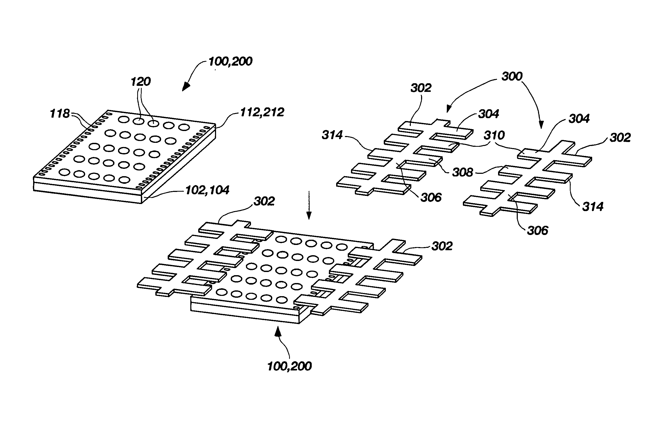
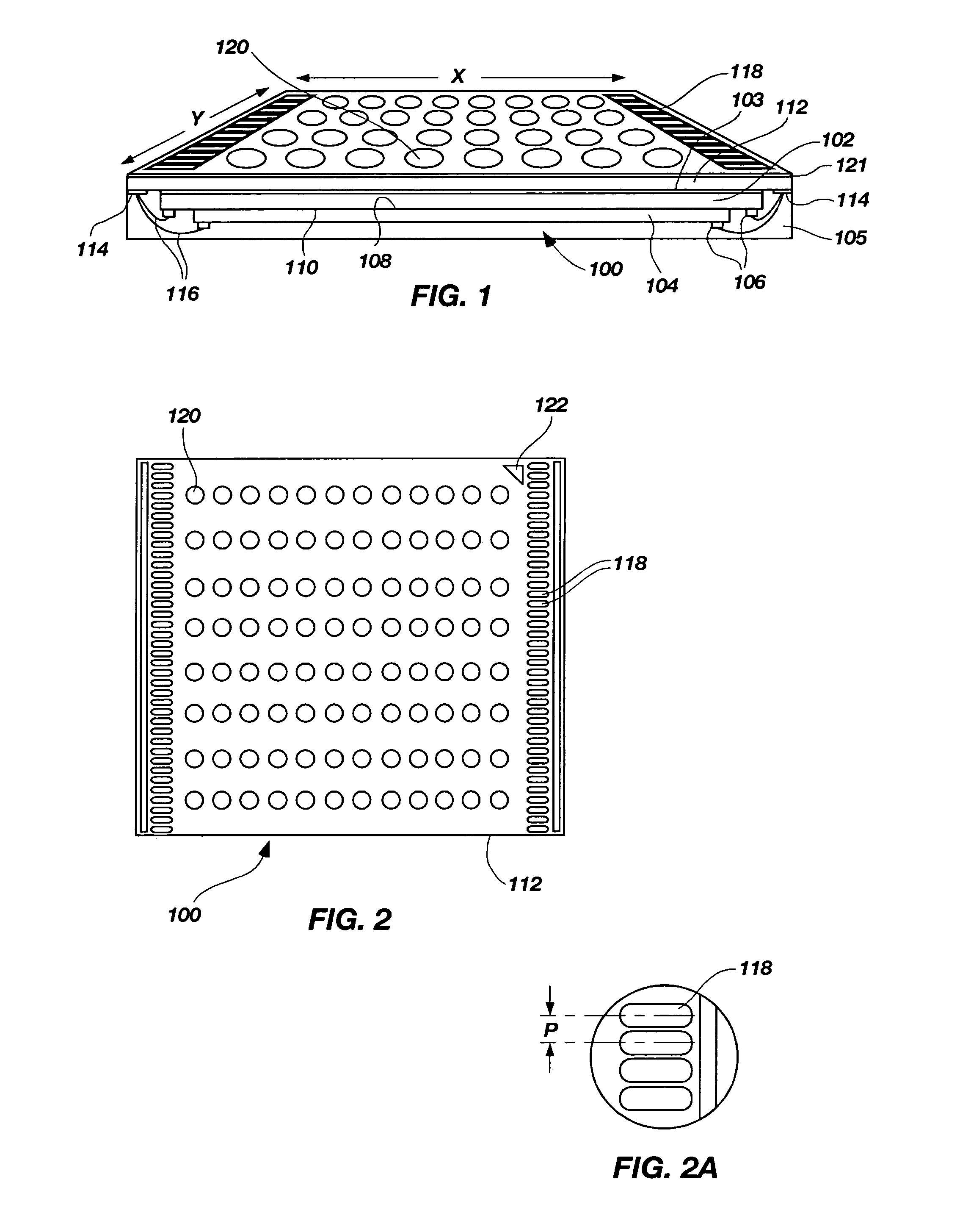
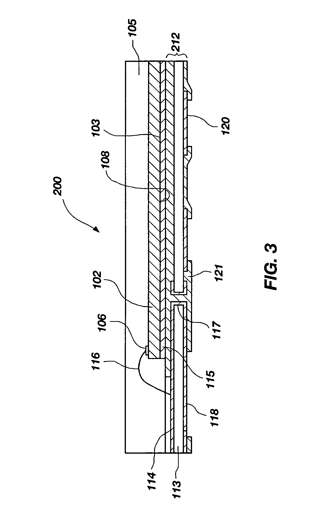
[0027]Referring now to FIG. 1 of the invention, land grid array package 100 comprises first and second semiconductor dice 102 and 104, each of which bears bond pads 106 adjacent opposing peripheral edges thereof, according to a selected pinout design, which may be customized using a redistribution layer to relocated inner lead bond locations to more peripheral, outer lead bond locations of bond pads 106. As can be seen in FIG. 1, semiconductor die 104 is slightly shorter in length than sem...


PUM


Abstract

A semiconductor device package includes a land grid array package. At least one semiconductor die is mounted to an interposer substrate, with bond pads of the semiconductor die connected to terminal pads on the same side of the interposer substrate as the at least one semiconductor die. Terminal pads of the interposer substrate may be electrically connected to either or both of a peripheral array pattern of lands and to a central, two-dimensional array pattern of pads, both array patterns located on the opposing side of the interposer substrate from the at least one semiconductor die. Additional components, active, passive or both, may be connected to pads of the two-dimensional array to provide a system-in-a-package. Lead fingers of a lead frame may be superimposed on the opposing side of the interposer substrate, bonded directly to the land grid array land and wire bonded to pads as desired for repair or to ease routing problems on the interposer. The land grid array package may be mounted to a carrier substrate, and the lands wire bonded to conductive pads on the carrier substrate. Methods of fabrication are also disclosed.

Description

BACKGROUND OF THE INVENTION[0001]1. Field of the Invention.[0002]The present invention relates generally to packaging of semiconductor devices and, more particularly, to semiconductor device packages incorporating a land grid array package therein, wherein the land grid array package may be configured to bear additional components, to enhance repairability, or both, as well as methods of fabricating such packages and related assemblies.[0003]2. Discussion of Related Art[0004]Semiconductor dice are becoming ever-smaller in dimension, both from advances in fabrication technology and as so-called “shrinks” of initial semiconductor die designs are developed to increase the number of dice which may be fabricated on a wafer or other bulk semiconductor substrate. As a consequence, it becomes more difficult to employ lead frame-based packaging techniques using, for example, wire bonds to directly connect bond pads of a die to lead fingers of a lead frame due to diminishing size of bond pads...

Claims


Application Information

Patent Timeline
Patent Type & Authority Patents(United States)
IPC IPC(8): H01L23/48
CPCH01L2924/01087H01L23/49861H01L2924/01079H01L23/49531H01L2225/06517H01L22/32H01L2224/32225H01L2224/48227H01L25/16H01L24/48H01L2224/73265H01L23/3121H01L2225/0651H01L24/92H01L2924/19041H01L25/50H01L2224/48091H01L24/97H01L24/96H01L22/14H01L2224/92127H01L2225/06527H01L25/0657H01L2224/97H01L24/73H01L2924/181H01L2924/00014H01L2924/00012H01L2924/00H01L2224/45099H01L2224/45015H01L2924/207H01L23/12H01L23/48
Inventor LEE, CHOON KUANCORISIS, DAVID J.CHONG, CHIN HUI
Owner MICRON TECH INC
Learn More