
Perpendicular magnetic recording medium with high medium S/N

a magnetic recording medium and perpendicular magnetic technology, applied in the field of magnetic recording mediums, can solve the problems of insufficient studies on weak scratch strength, and a lot of pit corrosion, and achieve excellent corrosion resistance and scratch resistance, excellent effect of high medium s/n

Inactive Publication Date: 2014-08-12
WESTERN DIGITAL TECH INC
View PDF15 Cites 0 Cited by
  • Summary
  • Abstract
  • Description
  • Claims
  • Application Information

AI Technical Summary

Benefits of technology

The solution achieves a high signal-to-noise ratio (S / N) while providing excellent corrosion and scratch resistance, effectively addressing the limitations of previous media by using a layered structure with specific alloy compositions and materials to enhance magnetic characteristics and environmental durability.

Problems solved by technology

As mentioned above, studies of the soft magnetic underlayer of a perpendicular magnetic recording medium have been carried out for the purpose of proposing a perpendicular magnetic recording medium suitable for high recording density, and sufficient studies have not been carried out looking at corrosion resistance and scratch resistance.
When the corrosion resistance and scratch resistance tests were performed using a composite assembly of a Co-based soft magnetic underlayer, a Ru intermediate layer, and an oxide granular type perpendicular magnetic recording layer which is well known as a perpendicular magnetic recording medium having a high medium S / N, it was discovered that the scratch strength was weak, a lot of pit corrosion was observed, and problems with corrosion resistance also surfaced.
A Co alloy does not only lack excellent corrosion resistance, but it also causes galvanic corrosion with the adjoining intermediate layer because it has an extremely negative potential in an aqueous solution environment.
Moreover, because there are many defects in an oxide granular type perpendicular magnetic recording layer which is well known as a recording layer, a protection effect cannot be obtained to carry out the corrosion inhibition of the soft magnetic underlayer although Ru or a Ru alloy has excellent corrosion resistance.

Method used


Image

  • Perpendicular magnetic recording medium with high medium S/N
  • Perpendicular magnetic recording medium with high medium S/N
  • Perpendicular magnetic recording medium with high medium S/N

Examples


embodiment 1

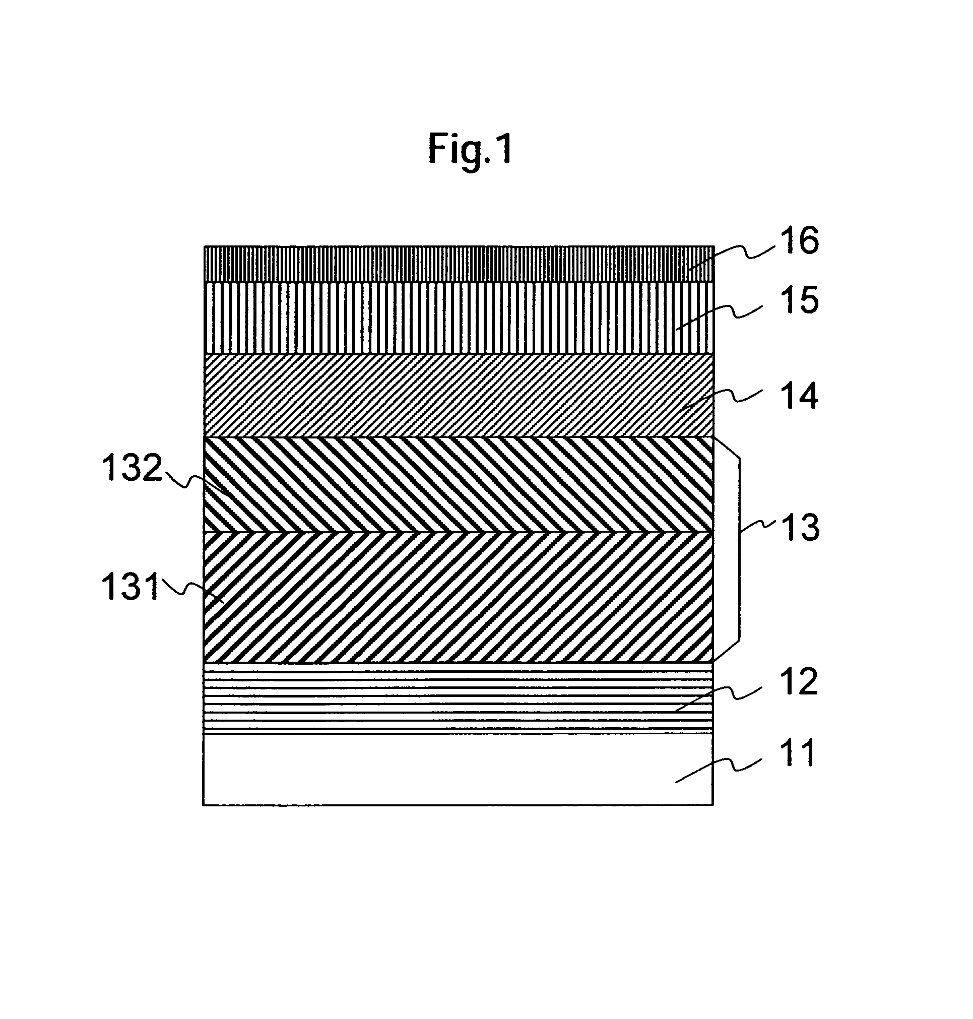
[0040]FIG. 1 is a layer configuration illustrating a perpendicular magnetic recording medium of this embodiment. A glass disk substrate with a thickness of 0.635 mm and a diameter of 65 mm (2.5 inch type) was used for the substrate 11 and an adhesion layer 12, a second soft magnetic layer 131, a first soft magnetic layer 132, an intermediate layer 14, a perpendicular recording layer 15, and a protective layer 16 were formed, in order, by using a sputtering technique. The soft magnetic layers 131 and 132 form a soft magnetic underlayer 13. The composition of each layer, the Ar gas pressure, and the film thickness used in this embodiment are shown in Table 1.

[0041]

TABLE 1Ar-gasThick-CompositionpressureRateness(at. %)(Pa)(nm / s)(nm)Adhesion layer 12Ni62.5Ta37.51530Soft2nd softCo92Ta3Zr50.512.550-100magneticmagneticunderlayerlayer 131131st softCo80Ta10Zr100.512.5 0-50magneticlayer 132Intermediate layer 14Ru20.320Recording layer 15CoCr13Pt14—SiO22116Protective layer 16Carbon0.615

[0042]Fir...

embodiment 2

[0054]A medium which had the same layer configuration as the medium 1-1 of the embodiment 1 and had a different second soft magnetic layer 131 and first soft magnetic layer 132 was fabricated, and the corrosion resistance and read / write characteristics were evaluated by using the same means as the embodiment 1. The composition, the film thickness, and the deposition process of each layer, except for the soft magnetic underlayer 13, were the same as the medium 1-1 of the embodiment 1. The results are shown in Table 4.

[0055]In the media from 2-1 to 2-7, the second soft magnetic layer 131 was fixed to be 92Co-3Ta-5Zr (at. %) and the material of the first soft magnetic layer 132 was changed. In the media from 2-1 to 2-4, Hf, Si, or Cr was added instead of Ta and Zr in the CoTaZr alloy. Moreover, in the media from 2-5 to 2-7, Ni or Fe was added in lieu of Co. Excellent corrosion resistance at rank B or higher could be obtained in each medium. Specifically, as shown in media 2-3 and 2-4, ...

embodiment 3

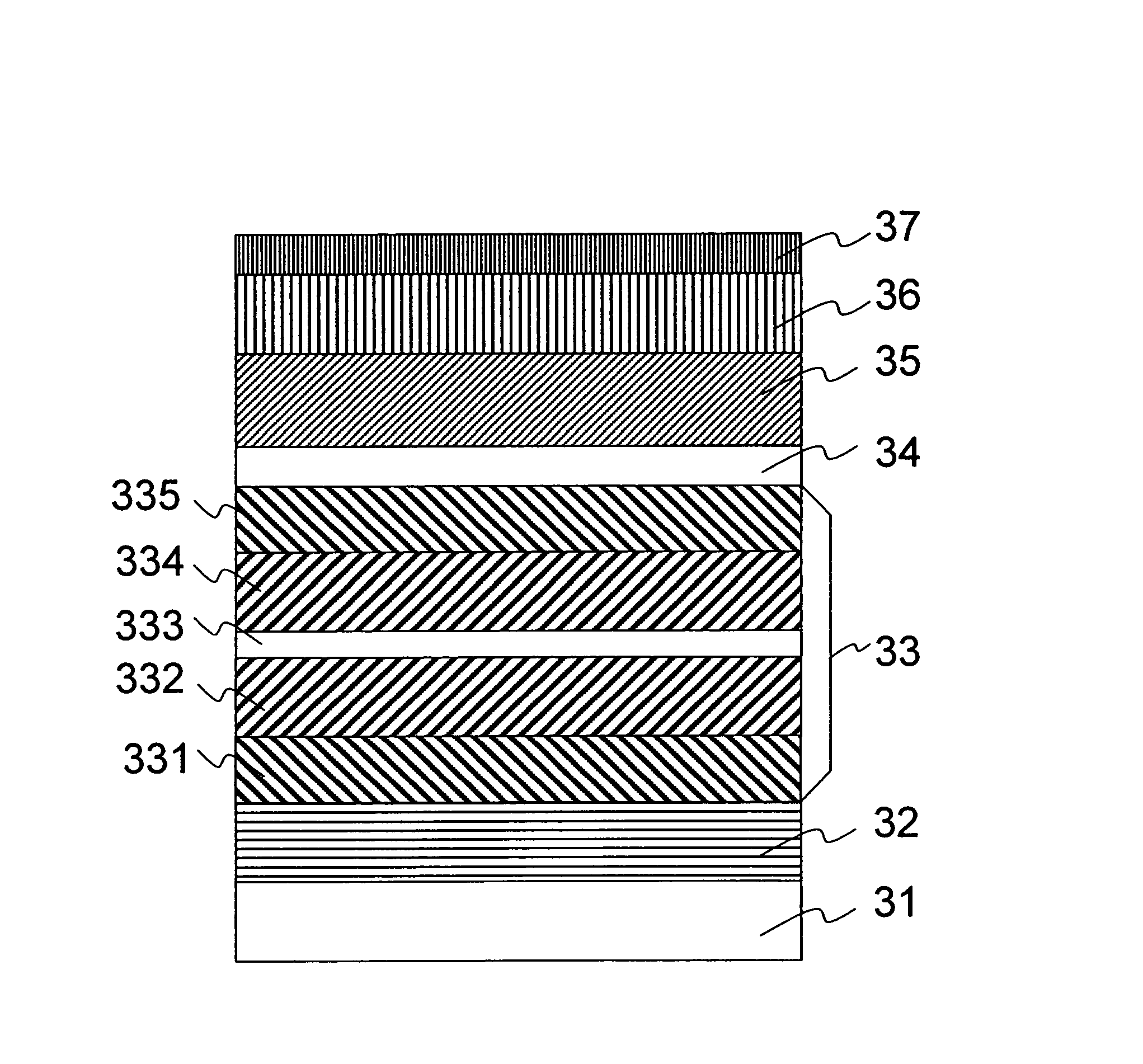
[0061]FIG. 7 is a layer configuration illustrating a perpendicular magnetic recording medium of this embodiment. A textured glass substrate with a thickness of 0.635 mm and a diameter of 65 mm (2.5 inch type) on which concentric circular shaped valley was formed on the surface was used for a substrate 21, and an adhesion layer 22, a third soft magnetic layer 231, a non-magnetic layer 232, a second soft magnetic layer 233, a first soft magnetic layer 234, a seed layer 24, an intermediate layer 25, a perpendicular recording layer 26, and a protective layer 27 were formed, in order, thereon by using a sputtering technique. Table 5 shows the target and the Ar gas pressure used for the fabrication of each layer and the film thickness.

[0062]

TABLE 5Ar-gasThick-CompositionpressureRateness(at. %)(Pa)(nm / s)(nm)Adhesion layer 22Ni62.5Ta37.51530Soft3rd softCo88Ni5Zr70.512.550magneticmagneticunderlayerlayer 23123nonmagneticRu10.70.8layer 2322nd softCo88Ni5Zr70.512.54-45magneticlayer 2331st softC...


PUM

PropertyMeasurementUnit
thicknessaaaaaaaaaa
thicknessaaaaaaaaaa
thickaaaaaaaaaa

Abstract

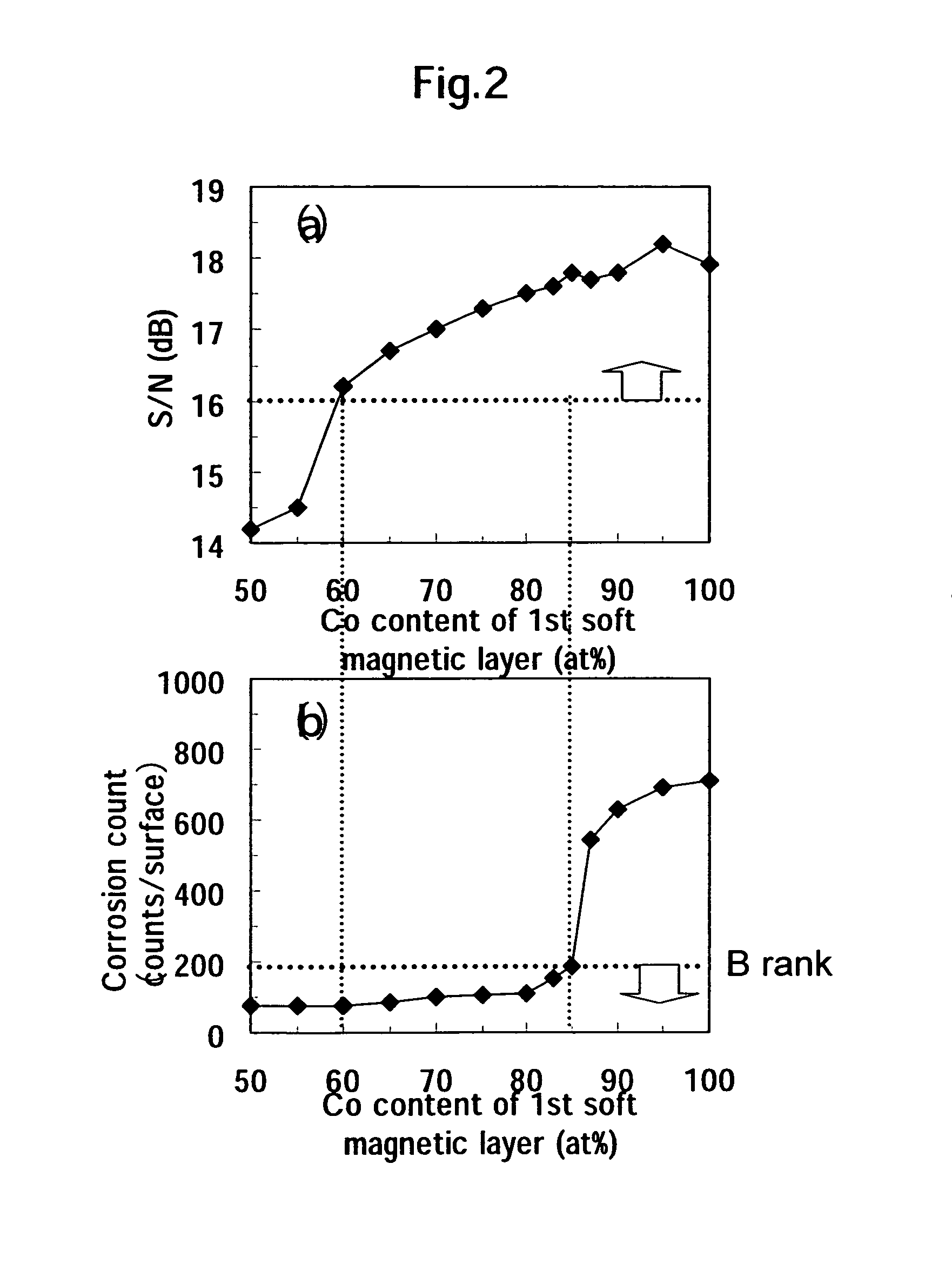
A medium having high medium S / N and excellent corrosion resistance is achieved. In one embodiment, an adhesion layer, a soft magnetic layer, an intermediate layer, a magnetic recording layer, and a protective layer are deposited, in order, on a substrate. The soft magnetic underlayer consists at least of two soft magnetic layers, the first soft magnetic layer formed on the recording layer side being composed of an amorphous alloy containing 85 at. % or less of Co, and the second soft magnetic layer formed on the substrate side being composed of an alloy containing more than 85 at. % of Co.

Description

CROSS-REFERENCES TO RELATED APPLICATIONS[0001]This application claims priority from Japanese Patent Application No. JP2005-302221, filed Oct. 17, 2005, the entire disclosure of which is incorporated herein by reference.BACKGROUND OF THE INVENTION[0002]The present invention relates to a magnetic recording medium which is available for high density information recording and specifically to a magnetic recording medium suitable for high density magnetic recording.[0003]Recently, in compact high capacity magnetic disk drives which are installed in both personal computers and home electric appliance there has been a strong demand to increase the capacity of the magnetic recording / reproducing apparatus and to improve the recording density. In order to respond to this demand, magnetic heads and magnetic recording media are being developed aggressively. However, it has become difficult to improve the recording density by using a longitudinal magnetic recording method which is the current com...

Claims


Application Information

Patent Timeline
Patent Type & Authority Patents(United States)
IPC IPC(8): G11B5/66G11B5/667
CPCG11B5/667G11B5/678G11B5/672
Inventor MATSUMOTO, HIROYUKISHODA, MITSUHIROARAI, REIKOHOSOE, YUZURUMABUCHI, KATSUMI
Owner WESTERN DIGITAL TECH INC
Learn More