Magnetic recording medium

a recording medium and magnetic technology, applied in the field of magnetic recording mediums, can solve the problems of not always being able to improve bit errors and reduce thermal fluctuation, and achieve the effects of excellent thermal fluctuation, excellent overwriting characteristic, and high medium s/n

Inactive Publication Date: 2006-10-12
HITACHI GLOBAL STORAGE TECH NETHERLANDS BV
View PDF15 Cites 4 Cited by
  • Summary
  • Abstract
  • Description
  • Claims
  • Application Information

AI Technical Summary

Benefits of technology

[0013] The present invention can provide a longitudinal magnetic recording medium that has high medium S / N, and provides excellent overwriting characteristic, excellent thermal fluctuation and sufficient stability against thermal fluctuation. Further, a combination of the medium with a magnetic head with high density can attain an in-plane recording density of 95 Mbits per 1 mm2.

Problems solved by technology

In the magnetic recording medium described in the Patent Document 1, in a case where an intermediate layer of a higher oxygen concentration compared with that of the plural magnetic layers is present between each of the plural magnetic layers, it is not always possible to improve bit errors and reduce thermal fluctuation.

Method used


Image

  • Magnetic recording medium
  • Magnetic recording medium
  • Magnetic recording medium

Examples


embodiment 1

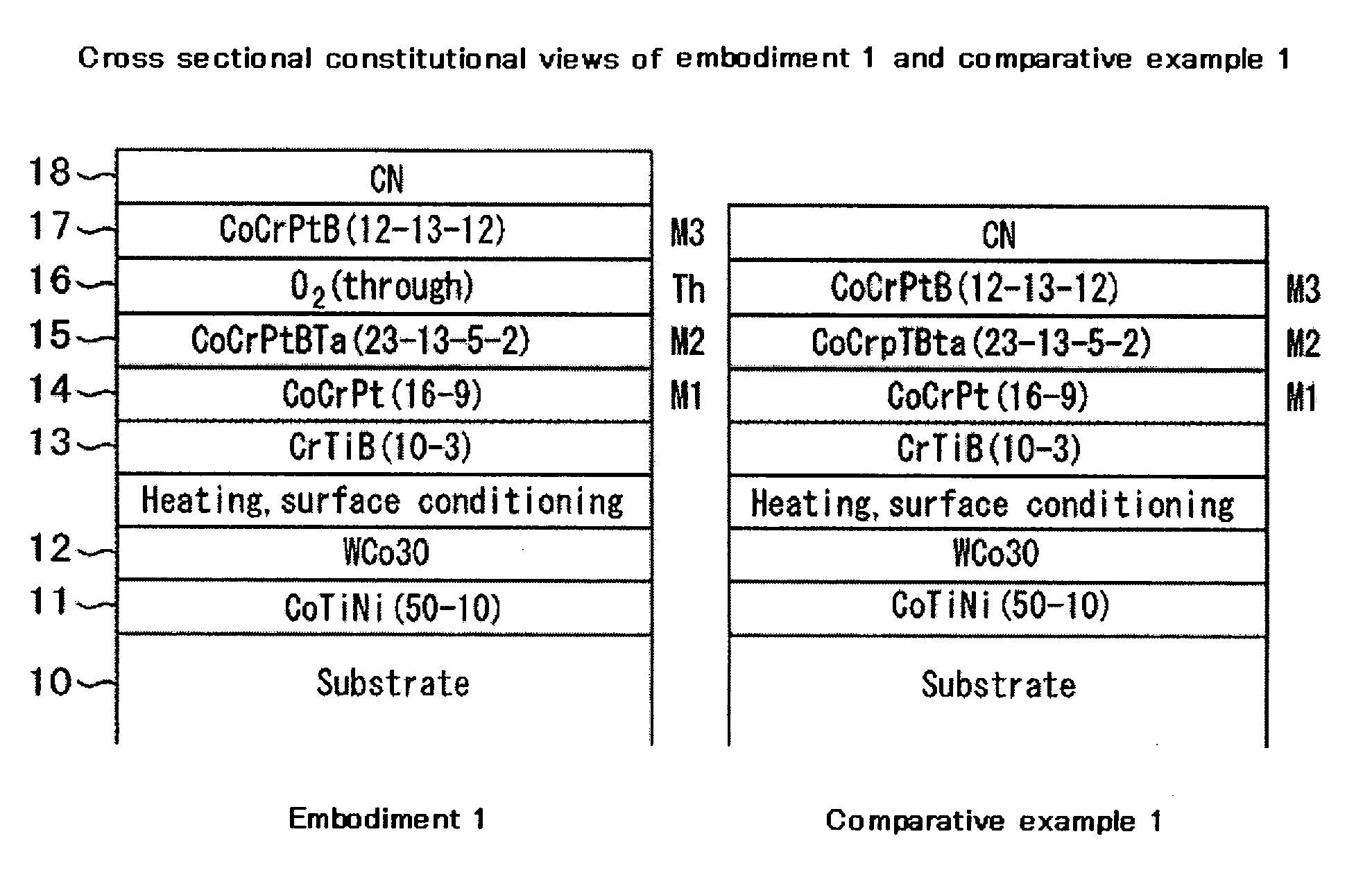
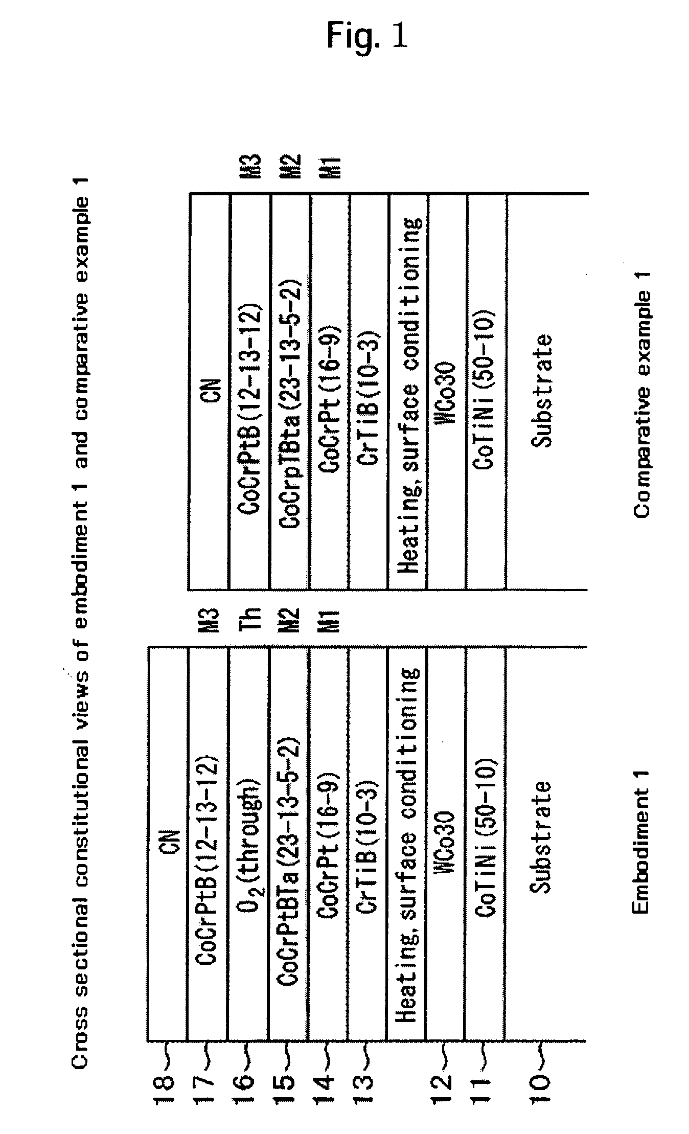
[0022]FIG. 1 shows cross sectional constitutions of embodiment 1 and comparative example 1. A magnetic recording medium of embodiment 1 includes underlayer films (11, 12, 13), a first magnetic layer 14, a second magnetic layer 15, a third magnetic layer 17, and a protective film 18, which are laminated over a substrate 10. In addition, an intermediate layer (Th) of a higher oxygen concentration than that of the magnetic layers is provided between the second magnetic layer 15 and the third magnetic layer 17. Although not illustrated, a lubrication film may also be formed on the protective film 18.

[0023] It is preferred to use, as the substrate 10, a chemically reinforced glass substrate, or a rigid substrate in which a phosphorus-containing nickel alloy is plated on an aluminum alloy. It is preferred in view of providing magnetic anisotropy to apply fine texturing on the substrate substantially in the circumferential direction of a disk. The substrate 10 may measure 84 mm in outer d...

embodiment 2

[0045] In embodiment 2, a magnetic recording medium was formed in the same manner as in Example 1 except for changing the thickness of the first magnetic layer (M1) 14 and its magnetic characteristic and electromagnetic conversion characteristic were evaluated. FIG. 4 shows the results. Brt of the medium increased along with increase of the film thickness tM1 of the first magnetic layer 14. Hcr was the maximum near 0.6 mm of the thickness of the first magnetic layer 14 and it was greatly decreased to 280 kA / m or less along with increase of the film thickness as the thickness of the first magnetic layer 14 exceeded 1.5 nm. At the thickness of the first magnetic layer 14 of about 1.0 to 1.5 nm, kNdHf was decreased most and BER was decreased to −5.1 or less. Also in a case where the thickness of the first magnetic layer was 1.8 nm, satisfactory BER that was near the case of the film thickness of about 1.0 to 1.5 nm was obtained.

[0046] As the thickness of the first magnetic layer was 0...

embodiment 3

[0047] Recording media are formed in the same manner as in embodiment 1 by forming the second magnetic layer (M2) 15 with a thickness of 11.4 nm comprising a Co-22at. % Cr-14at. % Pt-6at. % B-2at. % Ta alloy, instead of the second magnetic layer (M2) 15 used in embodiment 1, and then exposing them to a gas with addition of 1 mol % oxygen 02 to argon Ar for 2.5 sec. FIG. 5 shows a cross sectional structure of embodiment 3. The pressure of the gas introduced to the film forming chamber is changed from 0 Pa (no addition) to 1.87 Pa upon exposure of M3 in FIG. 5 to argon containing 1 mol % of oxygen.

[0048] The electromagnetic conversion characteristic was evaluated in combination with a composite type head having a recording electromagnetic induction magnetic head and a reading spin valve type magnetic head together on a spin stand. In this embodiment, evaluation was conducted by using a head different from the head used in embodiment 1. The head writing current was set to 37 mA and se...


PUM

PropertyMeasurementUnit
thicknessaaaaaaaaaa
thicknessaaaaaaaaaa
thicknessaaaaaaaaaa

Abstract

A magnetic recording material is provided which has high medium S/N, and provides excellent overwriting characteristic, excellent thermal fluctuation and sufficient stability against thermal fluctuation. In one embodiment, a first underlayer comprising one of alloys of a Ti—Co alloy, a Ti—Co—Ni alloy, and an Ni—Ta alloy, a second underlayer comprising a W—Co alloy or Ta, and a third underlayer of a body-centered cubic structure comprising a Cr—Ti—B alloy or a Cr—Ti alloy are disposed over a substrate. A first magnetic layer comprising a Co—Cr—B alloy or a Co—Cr—Ta alloy, a second magnetic layer comprising a Co—Cr—Pt—B—Ta alloy, a third magnetic layer comprising a Co—Cr—Pt—B alloy, and a protective film are disposed further thereover. An intermediate region (Th) is disposed between the second magnetic layer and the third magnetic layer, the intermediate region having a higher oxygen concentration than those of the magnetic layers.

Description

CROSS-REFERENCES TO RELATED APPLICATIONS [0001] This application claims priority from Japanese Patent Application No. JP2005-11 1774, filed Apr. 8, 2005, the entire disclosure of which is incorporated herein by reference. BACKGROUND OF THE INVENTION [0002] The present invention relates to magnetic recording media capable of recording a great amount of data and, more particularly, to a magnetic recording medium suitable for magnetic recording with high-density. [0003] A demand for magnetic disk drives with larger capacity has been increased more and more. In order to meet the demand, it has been required to develop magnetic heads with high-sensitivity and magnetic recording media with high-S / N. To improve the S / N of a medium, it is necessary to improve the read output for data that has been recorded at high-density. Generally, a magnetic recording medium comprises a first underlayer referred to as a seed layer formed on a substrate, a second underlayer of a body centered cubic struct...

Claims


Application Information

Patent Timeline
Patent Type & Authority Applications(United States)
IPC IPC(8): G11B5/66
CPCG11B5/656G11B5/7325G11B5/66G11B5/7368G11B5/7369
Inventor SUZUKI, HIROYUKIKASHIWASE, HIDEKAZUHINOUE, TATSUYAYAMAMOTO, TOMOO
Owner HITACHI GLOBAL STORAGE TECH NETHERLANDS BV
Why Eureka
Try Eureka