Hydraulic cylinder and method for the manufacture thereof

a technology of hydraulic cylinders and close-off parts, which is applied in the direction of engines without rotary main shafts, machines/engines, mechanical apparatuses, etc., can solve the problems of only being able to mount the close-off member, laborious and time-consuming, and dirt will be able to collect at the location, so as to simplify the assembly process and reduce the risk of dirt entrapment and assembly errors.

Inactive Publication Date: 2014-08-19
POWER PACKER NORTH AMERICA INC
View PDF5 Cites 11 Cited by
  • Summary
  • Abstract
  • Description
  • Claims
  • Application Information

AI Technical Summary

Benefits of technology

[0018]The invention proposes using a peripheral clamping ring made of resilient, compressible material instead of the steel snap ring containing a division seam. As a result, the way in which the cylinder is produced can be greatly simplified and the drawbacks in the field of soiling (hygiene) can be eliminated. In particular, the clamping ring can already be placed on the close-off member before that close-off member is inserted into the open end. This does not necessitate any particular equipment and the placing of the clamping ring can be carried out at an earlier moment than the coupling of the close-off member. The clamping ring is compressed in the axial direction during this mounting, so that good coupling between the coupling means can be attained. In addition, the clamping ring, which is clamped in a state compressed in the axial direction and between the flange and the open end, will exert on the closing member a force which strengthens the coupling between the cylinder body and close-off member. In addition, as a result of the fact that the clamping ring is clamped in compressed form between the flange and the open end, there will be no play, that is to say, no gaps between the clamping ring and flange, on the one hand, and / or the clamping ring and open end, on the other hand, and thus no dirt can accumulate therein. This is particularly advantageous in medical applications, where for example an autoclave is used in order, for example, to clean the bed with the hydraulic cylinder(s). In addition, the invention allows a close-off member to be mounted on both sides of a cylinder (body).
[0026]In particular, the method provides the possibility of coupling the cylinder body and the close-off member directly to each other, wherein the only operation which has to be carried out is the telescoping of both components and causing them to couple with each other by means of the coupling means provided. Both the cylinder body and the close-off member can be fully provided with all the required components prior to the mutual coupling. This greatly simplifies the assembly process and the risk of entrapment of dirt and the risk of errors during assembly are reduced to a minimum.

Problems solved by technology

It is a drawback of this hydraulic cylinder known from U.S. Pat. No. 6,263,779 with a close-off member and this known method for coupling the close-off member that the placing of the steel snap ring takes place once the close-off member is already coupled to the cylinder body.
This is laborious and time-consuming.
Furthermore, DE 44 33 649 A1 has the drawback that mounting of the close-off member is only possible by introducing the close-off member via a first open end in the cylinder into the interior thereof and subsequently by displacing the cylinder to the second open end of the cylinder to which the close-off member has to be fastened.
In addition, it is a drawback both of U.S. Pat. No. 6,263,77 and of DE 44 33 649 A1 that dirt will be able to collect at the location of the steel snap ring.
This is very disadvantageous, in particular when the hydraulic cylinder is used in a medical application, for example for a hydraulically adjustable hospital bed.
Cleaning of the hydraulic cylinder is then impeded, as the dirt is situated in locations which are very difficult to reach and cannot be removed or can be removed only with difficulty.

Method used


Image

  • Hydraulic cylinder and method for the manufacture thereof
  • Hydraulic cylinder and method for the manufacture thereof
  • Hydraulic cylinder and method for the manufacture thereof

Examples


Embodiment Construction

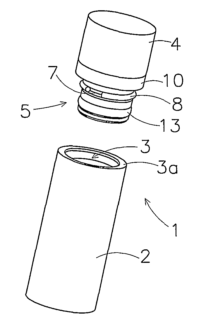
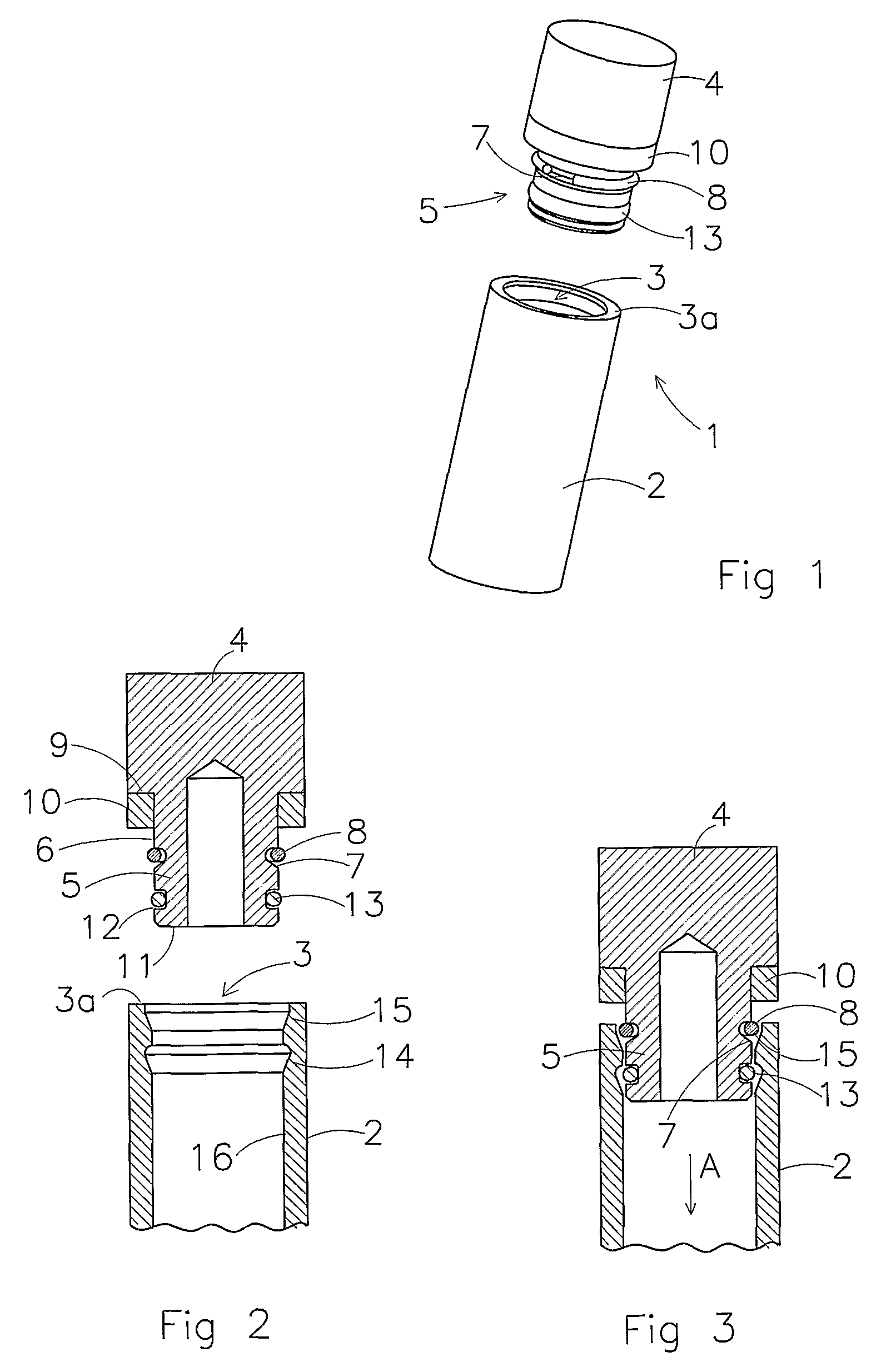
[0035]FIG. 1 is a three-dimensional representation, with exploded parts, of a portion of a hydraulic cylinder denoted in its entirety by reference numeral 1. The cylinder 1 has a cylinder body 2 which at one end is closed off by a close-off member 4 which will be described in greater detail. A gland, through which the piston rod (not shown) of the hydraulic cylinder protrudes, is attached to the cylinder body 2 at the other end (not shown). The cylinder body 2 is made of a suitable metal, preferably of aluminium, preferably by extrusion of the cylinder body as tubing having a uniform cross section longitudinally, which tubing subsequently undergoes one or more treatments.

[0036]The cylinder body 2 has an open end 3 with an opening and an edge 3a lying therearound. On the inside, the cylinder body 2 has an inner surface.

[0037]The close-off member 4 has an insert part 5 which is configured to be introduced into the open end 3 of the cylinder body 2. Furthermore, the close-off member 4 ...


PUM

PropertyMeasurementUnit
compressibleaaaaaaaaaa
radiusaaaaaaaaaa
depthaaaaaaaaaa

Abstract

A hydraulic cylinder comprising:a cylinder body which has an open end with an opening and an edge extending therearound, which cylinder body also has an inner surface;a piston rod;a close-off member which has an insert part, which insert part protrudes in a fitting manner into the open end of the cylinder body, which insert part has an outer circumferential face, wherein the close-off member also has a flange opposing the edge of the cylinder body;coupling means which are operable between the inner surface of the cylinder body and the outer circumferential face of the insert part for securing, in at least one axial direction, the close-off member in the cylinder body, anda clamping ring which is clamped between the flange and the edge at the open end of the cylinder body.The clamping ring is made of a resilient, compressible material, in particular is made of an elastomer. The clamping ring is clamped, when compressed in the axial direction, between the flange and the edge at the open end.

Description

CROSS-REFERENCE TO RELATED APPLICATIONS[0001]This application is a national stage filing under 35 U.S.C. 371 of PCT International Application No. PCT / NL2009 / 000065 filed on Mar. 18, 2009, which claims foreign priority to Netherlands Patent Application No. 2001389 filed Mar. 19, 2008, the entire contents of all of which are incorporated herein by reference. Priority to each application is hereby claimed.FIELD OF THE INVENTION[0002]The present invention relates to a hydraulic cylinder. The present invention also relates to a method for coupling a close-off member to a cylinder body of a hydraulic cylinder.BACKGROUND OF THE INVENTION[0003]A cylinder having a close-off member mounted thereon is for example known from US patent publication U.S. Pat. No. 6,263,779. That document describes a method for coupling a close-off member, such as a close-off cover or a gland, for guiding a piston rod of a hydraulic damper of a vehicle suspension system, with a cylinder body of a damper of this typ...

Claims


Application Information

Patent Timeline
Patent Type & Authority Patents(United States)
IPC IPC(8): F15B15/14
CPCF15B15/1438F15B15/1433Y10T29/494
Inventor BEUMER, JAN, ALBERTUS
Owner POWER PACKER NORTH AMERICA INC
Why Eureka
Try Eureka