Method of joining superconductor materials

a superconductor material and superconductor technology, applied in the direction of superconductor details, layered products, chemistry apparatus and processes, etc., can solve the problems of superconductor lead loss, energy consumption, and affect the performance of a superconducting product thereo

Active Publication Date: 2014-08-19
IND TECH RES INST
View PDF15 Cites 4 Cited by
  • Summary
  • Abstract
  • Description
  • Claims
  • Application Information

AI Technical Summary

Benefits of technology

[0006]Apart from this, high-temperature superconductor materials are almost in a complex structure of ceramic oxide materials. For the bonding between conventional ceramic materials, a fluxing agent may be used to lower a bonding temperature of ceramic (lower than a sintering temperature thereof). However, although the ceramic can be bonded together, the interface structure is changed, and thus is incapable of being the same as that of the origin material. Therefore, a rather large resistance value definitely exists on the bonding interface.

Problems solved by technology

If the length of the superconductive lead is further extended, the performance of a superconductive product thereof is affected after being used for a long time.
Therefore, heat may be inevitably generated during a long time of running to cause the consumption of energy, even make the superconductive lead lose its conductivity.
Hence, the whole quality of the superconductive transmission line is affected.
However, although the ceramic can be bonded together, the interface structure is changed, and thus is incapable of being the same as that of the origin material.

Method used


Image

  • Method of joining superconductor materials
  • Method of joining superconductor materials
  • Method of joining superconductor materials

Examples


Embodiment Construction

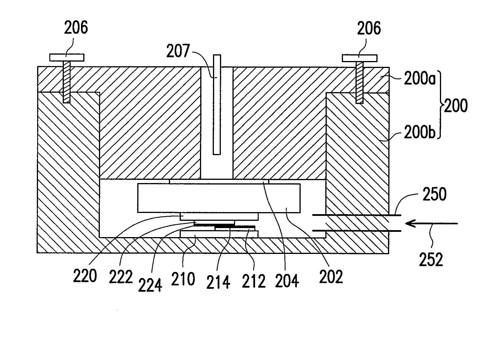
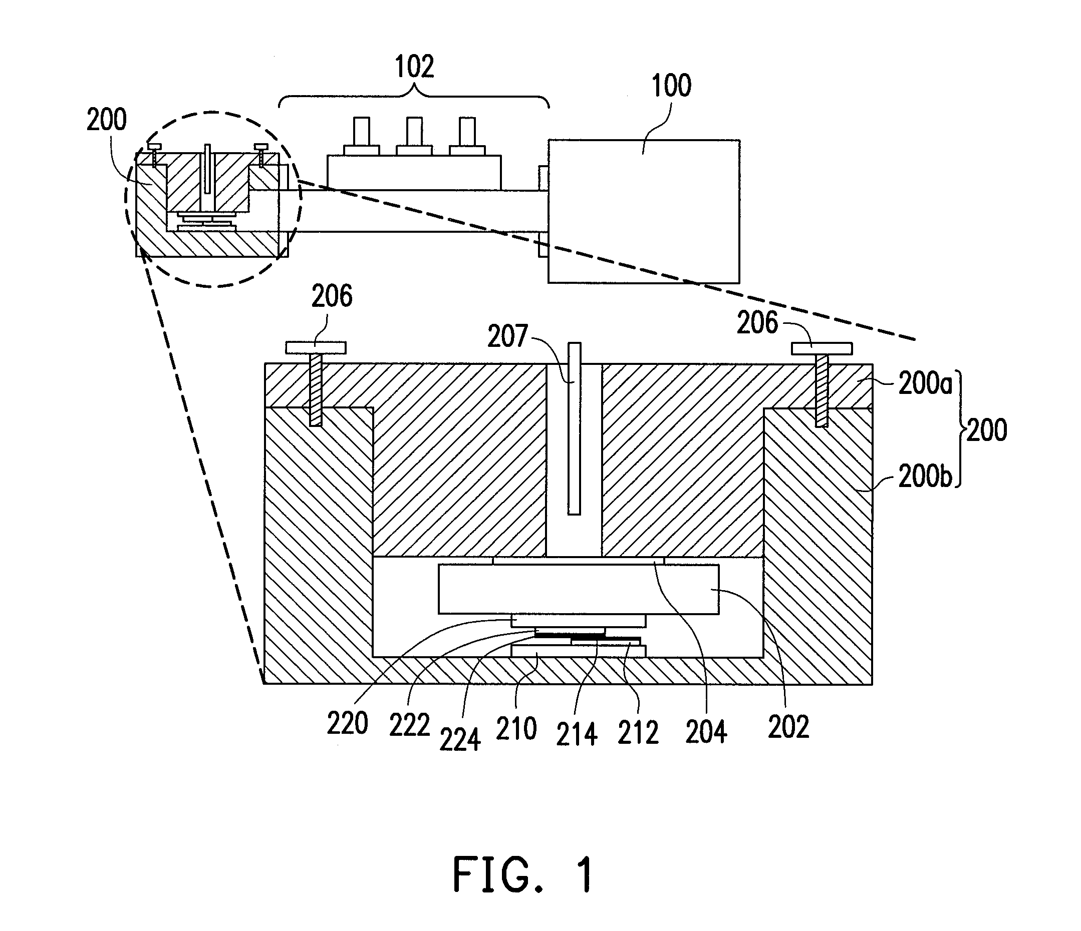
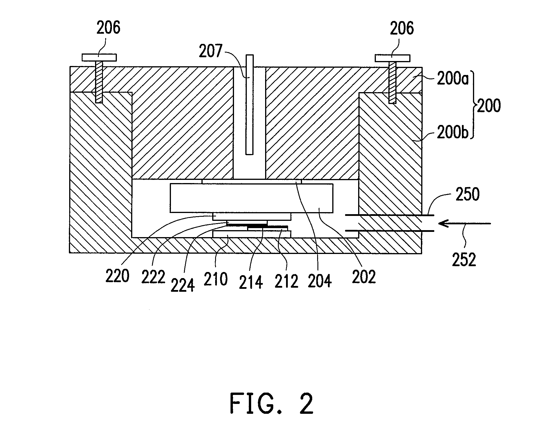
[0015]FIG. 1 is a schematic diagram of a method of joining superconductor materials according to an exemplary embodiment of the disclosure. Referring to FIG. 1, first a microwave chamber 200 is provided. Additionally, the microwave chamber 200 is connected to a microwave generator 100 through a waveguide device 102. The microwave generator 100 can generate microwave power with different levels. The generated microwave power enters the microwave chamber 200 through the waveguide device 102, and may generate a resonance and focusing effect in the microwave chamber 200.

[0016]In this exemplary embodiment, the microwave chamber 200 is a closed space formed of an upper structure 200a and a lower structure 200b. Additionally, a first heat absorption plate 210 and a second heat absorption plate 220 are disposed in the microwave chamber 200. The first heat absorption plate 210 and the second heat absorption plate 220 are made of a plate material capable of absorbing the microwave power and r...


PUM

PropertyMeasurementUnit
thicknessaaaaaaaaaa
lengthaaaaaaaaaa
poweraaaaaaaaaa

Abstract

A method of joining superconductor materials is described. A microwave chamber including a first heat absorption plate and a second heat absorption plate corresponding to the first absorption plate is provided. A first superconductor material and a second superconductor material are disposed between the first heat absorption plate and the second heat absorption plate in the microwave chamber. The first superconductor material and the second superconductor material have an overlapping region therebetween, and a pressure is applied to the first heat absorption plate and the second heat absorption plate. Microwave power is supplied to the microwave chamber. The first heat absorption plate and the second heat absorption plate transform the microwave power into thermal energy so as to join the first superconductor material and the second superconductor material at the overlapping region.

Description

CROSS-REFERENCE TO RELATED APPLICATION[0001]This application claims the priority benefit of Taiwan application serial no. 100147425, filed on Dec. 20, 2011. The entirety of the above-mentioned patent application is hereby incorporated by reference herein and made a part of this specification.BACKGROUND[0002]1. Technical Field[0003]The disclosure relates to a joining method, and in particular, to a method of joining superconductor materials.[0004]2. Related Art[0005]Based on the current industrial technologies, superconductor materials are joined by using copper metal as an assistant joining material. However, by using the joining type, a produced high-temperature superconductive lead of yttrium barium copper oxide (YBCO) can merely have a maximum length of 500 meters. If the length of the superconductive lead is further extended, the performance of a superconductive product thereof is affected after being used for a long time. The main reason is that although the resistance value of...

Claims


Application Information

Patent Timeline
Patent Type & Authority Patents(United States)
IPC IPC(8): H01L39/24
CPCH01L39/02C04B37/001C04B2237/341C04B2237/50C04B2237/82H01L39/24H10N60/80H10N60/01
Inventor HUANG, KUN-PINGCHANG, CHIH-CHENHSIEH, YU-TSELUO, CHIH-WEISU, CHIH-HSIANGTZENG, WEN-YEN
Owner IND TECH RES INST
Why Eureka
Try Eureka