Backlight sources having reduced thickness and liquid crystal display device using the same

a backlight source and liquid crystal display technology, applied in lighting and heating apparatus, manufacturing tools, instruments, etc., can solve the problems of difficult control or guarantee of the display brightness of the portion of the screen far away from the side light source, difficulty in ensuring the light guide plate, and limited so as to reduce the thickness of the backlight source, eliminate the limitation of the size of the liquid crystal panel, and minimize the effect of the thickness

Active Publication Date: 2014-08-19
APPOTRONICS CORP LTD
View PDF18 Cites 1 Cited by
  • Summary
  • Abstract
  • Description
  • Claims
  • Application Information

AI Technical Summary

Benefits of technology

[0013]The present invention aims to solve the technical problems and the shortcomings of the existing technologies mentioned above. Embodiments of the present invention provide a backlight source and a method to reduce its thickness which substantially eliminates the size limitation of the liquid crystal panel and minimizes the thickness of the backlight source so as to reduce the overall thickness of the LCD device, without compromising the uniformity of the outgoing light.
[0014]To address the above technical problems, the basic principles of the present invention are as followings. To make backlight sources adaptable to different sizes of liquid crystal panels, it is preferred to use solid state light sources, such as arrays of LEDs, and use back-coupling. Since the intensity of light emitted from LEDs generally follows the Lambertian distribution (cosine distribution), existing technologies use a large enough scattering space to ensure the uniform illumination of liquid crystal panels and prevent the occurrence of light spots. In embodiments of the present invention, the above light distribution is changed by reducing the intensity of small angle outgoing light and increasing the intensity of large angle outgoing light. Because large angle light has a longer light path and a larger range of irradiation when propagating forward, the uniform mixture of red, green, and blue light can be achieved in a smaller scattering space, which can reduce the thickness of the backlight source.

Problems solved by technology

For the first scheme of using light source side-coupling method, it is difficult for the light guide plate to ensure that the liquid crystal panel is uniformly illuminated when the size of liquid crystal panel is large.
The display brightness of the portion of the screen that is far away from the side light source is especially difficult to be controlled or guaranteed.
Even adopting double side-coupling for improvement, the size of the liquid crystal panel is still limited due to the non-uniformity of display brightness.
Besides, the total thickness of this type of backlight source depends on the width of the light source and the thickness of the light guide plate, and thus it is difficult to make it ultra thin.
For the second scheme of using light source back-coupling method, although it can overcome the screen size-limit problem mentioned above, the necessary existence of the scattering body or the scattering space not only reduces the light transmission efficiency but also increases the total thickness of the backlight module.
If the scattering body or the scattering space is reduced in order to make the device ultra thin, the occurrence of red, blue or green light spots may be unavoidable due to the insufficient mixture of red, green, and blue light.

Method used


Image

  • Backlight sources having reduced thickness and liquid crystal display device using the same
  • Backlight sources having reduced thickness and liquid crystal display device using the same
  • Backlight sources having reduced thickness and liquid crystal display device using the same

Examples


Embodiment Construction

[0035]Embodiments of the present invention are described in more detail below with reference to the drawings.

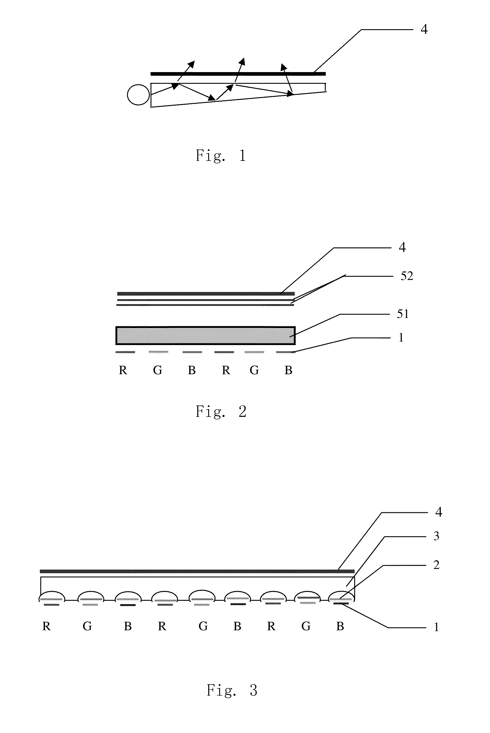
[0036]As described earlier, a method for a conventional backlight source to provide outgoing light includes the following steps:

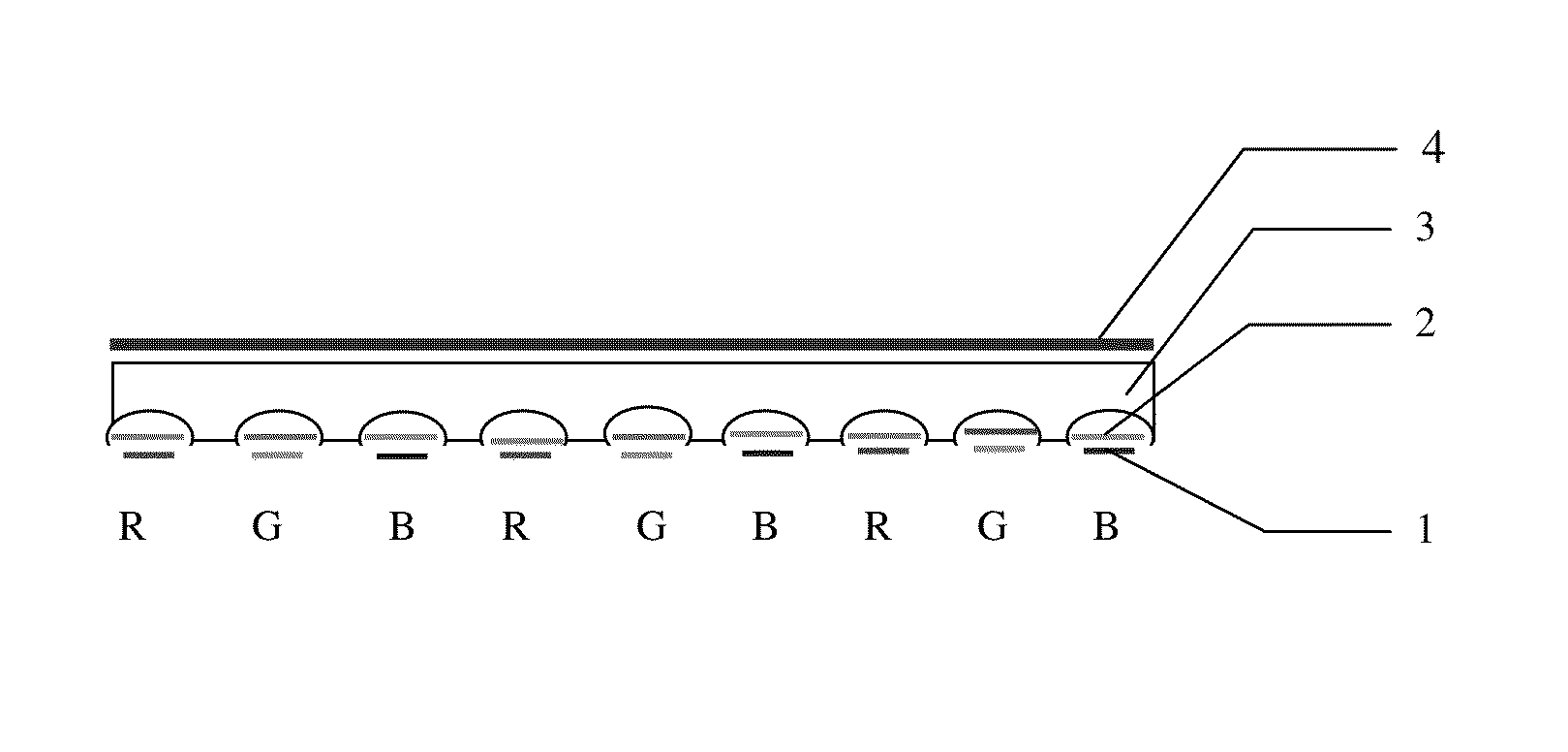
[0037]Providing a backlight source by placing an array of a plurality of solid state light sources below a light transmitting unit. The solid state light source may be an LED but is not limited thereto. The light transmitting unit may be a light guide plate but is not limited thereto.

[0038]Light emitted from the solid state light source transmits through the light transmitting unit, and provides outgoing light of the backlight source.

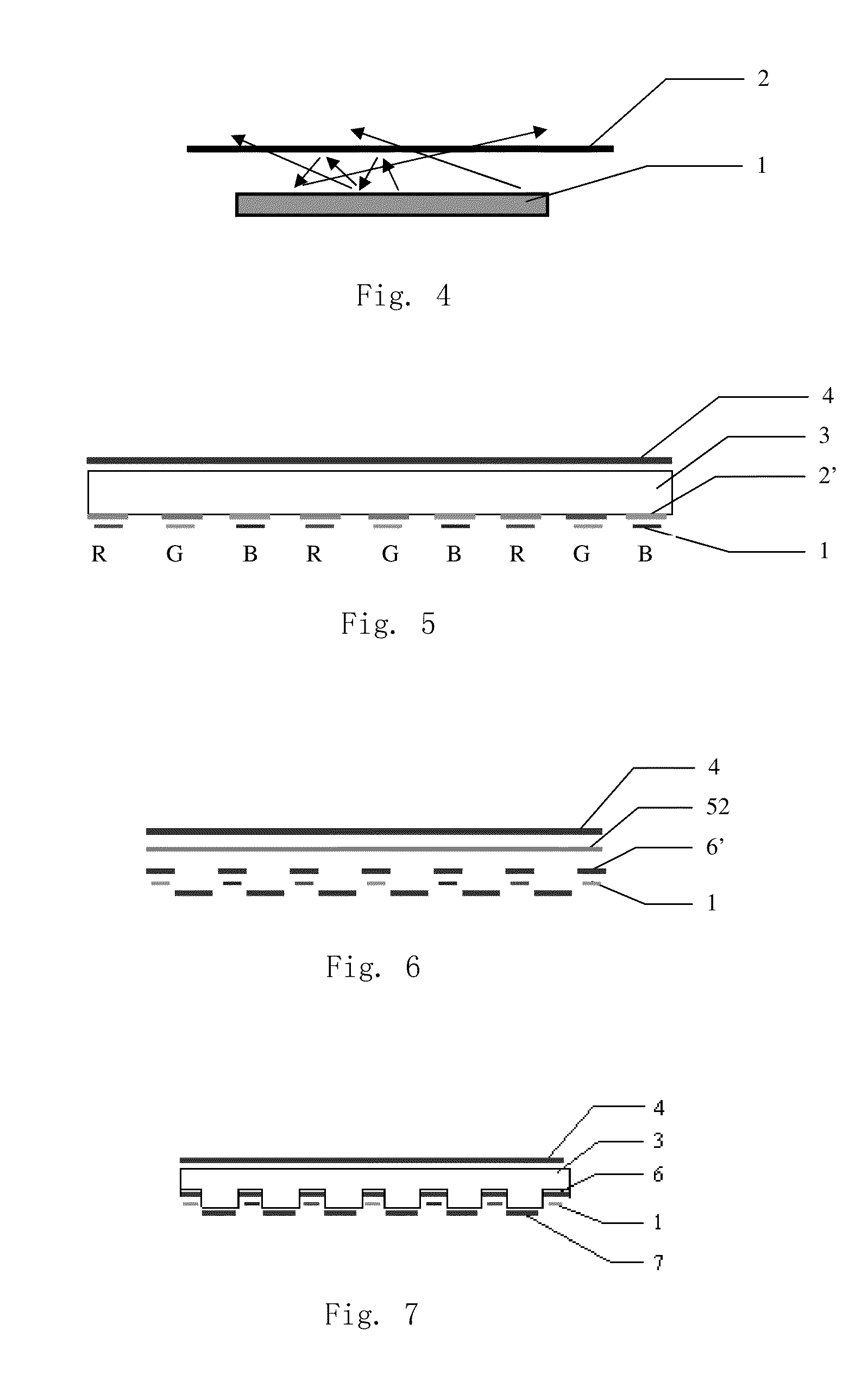
[0039]To reduce the thickness of a backlight source, a method according to embodiments of the present invention improves upon the above described method as follows:

[0040]Between the array of solid state light sources and the light transmitting unit, a plurality of light adjusting units are placed above the plurality of t...


PUM

PropertyMeasurementUnit
thicknessaaaaaaaaaa
refractive indexaaaaaaaaaa
incident anglesaaaaaaaaaa

Abstract

A backlight source and a thinning method for the same are provided. The backlight source includes: a solid state light source array having a plurality of solid state light sources distributed on the base, a light transmitting unit arranged above the solid state light source array, and a plurality of light adjusting units arranged between the solid state light source array and the light transmitting unit. The plurality of the light adjusting units is arranged above the plurality of solid state light sources to reflect the shallow angle incident light from the solid state light source, thus changes the light intensity distribution of the output light through the light transmitting unit from the solid state light sources from Lambertian distribution to main sides emission.

Description

[0001]This is a U.S. National Stage application of PCT / CN2010 / 000990, filed Jul. 1, 2010, which claims priority from Chinese patent application CN 200910108498.2, filed Jul. 1, 2009, both of which are herein incorporated by reference in their entireties.BACKGROUND OF THE INVENTION[0002]1. Field of the Invention[0003]This invention relates to a device to control the intensity or direction of light from independent light sources, and in particular, such a device useful in a backlight source of liquid crystal display (LCD) devices.[0004]2. Description of the Related Art[0005]A typical LCD device includes a light source system with a number of monochromatic light sources, such as and not limited to, red light source, green light source, and blue light source, generating red (R), green (G), and blue (B) lights, respectively. Because the liquid crystal can only modulate the light intensity but cannot produce light itself, the light source system is generally a surface light source that is...

Claims


Application Information

Patent Timeline
Patent Type & Authority Patents(United States)
IPC IPC(8): G02F1/1335F21V7/04G09F13/04
CPCG02B5/201G02F1/133603G02F1/133606G02F1/133611Y10T29/49826
Inventor LI, YI
Owner APPOTRONICS CORP LTD
Why Eureka
Try Eureka