Microchannel chip and method for gas-liquid phase separation using same

a microchannel chip and gas liquid phase separation technology, applied in the direction of photometry, optical radiation measurement, biological material analysis, etc., can solve the problems of deteriorating accuracy of ultra-fine process patterning, increasing the defect rate, and inability to prompt action, etc., to achieve good reproducibility and high sensitivity

Active Publication Date: 2014-08-26
KANAGAWA INST OF IND SCI & TECH +2
View PDF6 Cites 0 Cited by
  • Summary
  • Abstract
  • Description
  • Claims
  • Application Information

AI Technical Summary

Benefits of technology

[0026]By the present invention, a novel gas-liquid phase separation method capable of stably performing sufficient gas-liquid phase separation in a microchannel and a microchannel chip therefor were provided. By applying the gas-liquid separation method according to the present invention to the method described in Non-patent Document 1 or the like where a test gas is measured using a microchannel, a test gas can be measured in a short period of time with high sensitivity and good reproducibility.

Problems solved by technology

In cases where the air inside the clean room contains ammonia even in a low concentration of several ppb, the accuracy of ultra-fine process-patterning is deteriorated and the percent defective is increased.
However, this method requires about 3 days from the start of the measurement to acquisition of analytical result, including the time required for transferring the sample to an analysis center; therefore, prompt action cannot be taken even when the ammonia concentration becomes high.
In addition, the ammonia detection limit of this method is about 50 ppb, which is not sufficient.
However, in this method, the measurement reproducibility is low and the coefficient of variation (CV) of the measured values is 20%.

Method used


Image

  • Microchannel chip and method for gas-liquid phase separation using same
  • Microchannel chip and method for gas-liquid phase separation using same
  • Microchannel chip and method for gas-liquid phase separation using same

Examples


example 1

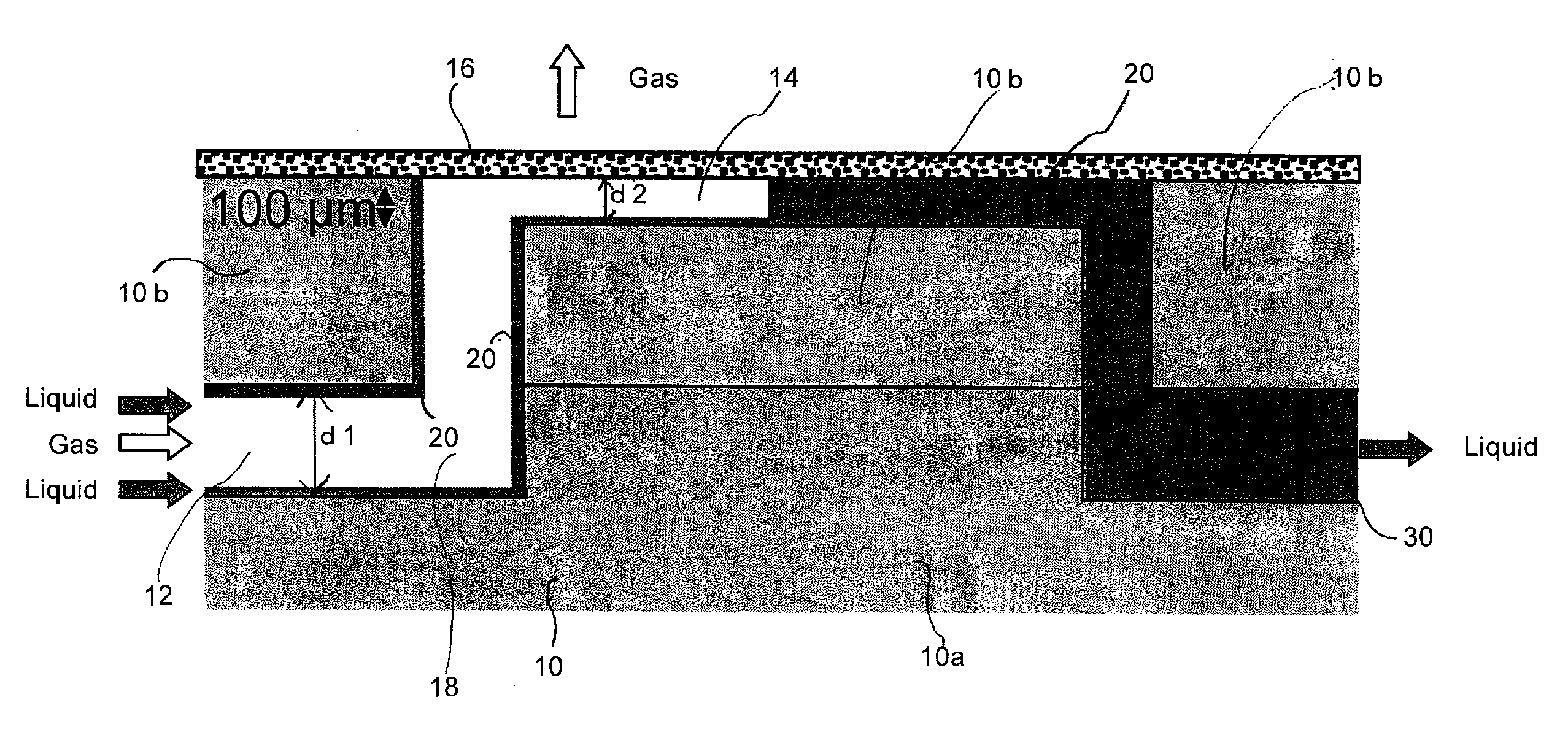
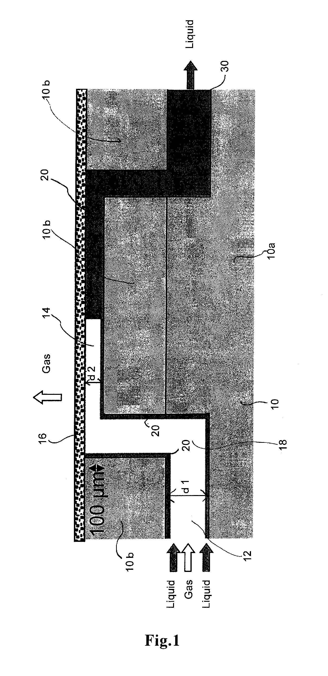
[0062]A microchannel chip having the gas-liquid phase separation microchannel shown in FIG. 1 was prepared. The schematic plan view thereof is shown in FIG. 4. To the test substance-measuring microchannel 30, an oxidizing solution introduction microchannel 34 and a coloring solution introduction microchannel 36 were connected. In the microchannel chip shown in FIG. 4, after allowing a collection solution to which ammonia gas was dissolved to pass through a gas-liquid phase separation part, the collection solution is once led to a tube arranged outside of the chip (indicated by a solid arrow in FIG. 4). The collection solution is then re-introduced to the channel inside the chip and combined with a coloring solution and an oxidizing solution and these are allowed to react in a further downstream of the microchannel. It is noted here that FIG. 4 shows a substrate on which microchannels are formed and that the microchannel of the part enclosed in a rectangle and indicated as “gas-liqui...


PUM

PropertyMeasurementUnit
depthaaaaaaaaaa
depthaaaaaaaaaa
porosityaaaaaaaaaa

Abstract

A microchannel chip having a microchannel formed in a substrate and a gas-liquid phase separation microchannel whose upper part is covered with a porous film, the gas-liquid phase separation microchannel being connected to the downstream end of the microchannel and having a depth of 10 μm to 100 μm. Also, a gas-liquid phase separation method which is a method for separating a liquid-phase flow from a two-phase flow flowing through a microchannel by removing a gas phase, the two-phase flow composed of the gas phase and the liquid phase, which liquid phase flows in the periphery of the above-described microchannel and which gas phase flows interiorly of the liquid-phase flow.

Description

TECHNICAL FIELD[0001]The present invention relates to a microchannel chip capable of separating a liquid-phase flow from a two-phase flow flowing in a microchannel by removing a gas-phase flow, the two-phase flow being composed of the gas-phase flow and the liquid-phase flow; and a gas-liquid phase separation method using the microchannel chip. The present invention also relates to a microchannel chip for measuring a gaseous test substance and a method of measuring a gaseous test substance.BACKGROUND ART[0002]In order to reduce the percent defective, semiconductor devices are manufactured in a clean room where dust and the like are present in an extremely small amount. It is required that the air inside such clean room be free from not only dust, but also ammonia. In cases where the air inside the clean room contains ammonia even in a low concentration of several ppb, the accuracy of ultra-fine process-patterning is deteriorated and the percent defective is increased. Therefore, the...

Claims


Application Information

Patent Timeline
Patent Type & Authority Patents(United States)
IPC IPC(8): B01D53/00
CPCB01L5/00B01L2400/0478Y10T436/17B01L3/502753B01D2325/04B01D53/22B01D19/0031Y10T436/173845B01L2300/0816B01D2325/38G01N35/08B01D71/36Y10T436/25375B01D69/02B01D2325/02Y10T436/175383
Inventor AOTA, ARATAKIHIRA, YUKOSASAKI, MARIKITAMORI, TAKEHIKOMAWATARI, KAZUMA
Owner KANAGAWA INST OF IND SCI & TECH
Why Eureka
Try Eureka