Cooling system of motor assembly for cleaner

a technology of motor assembly and cooling system, which is applied in the direction of vehicle cleaning, carpet cleaning, magnetism circuit shape/form/construction, etc., to achieve the effect of increasing reducing the size of the motor, and reducing the power of the motor

Inactive Publication Date: 2014-09-02
JOHNSON ELECTRIC SA
View PDF36 Cites 2 Cited by
  • Summary
  • Abstract
  • Description
  • Claims
  • Application Information

AI Technical Summary

Benefits of technology

[0019]By implementing the invention, the motor is cooled by the liquid coolant such as water inside a cooling pipe that is thermally coupled to the stator. Thus the size of the motor can be decreased without reducing the power of the motor or the power of the motor increased without increasing the size of the motor. In other words, the power density of the motor can be increased.

Problems solved by technology

Further more, in specified applications, there is not enough space for a channel or passage within the motor or stator for the air flow, preventing the heat from dissipating quickly.

Method used


Image

  • Cooling system of motor assembly for cleaner
  • Cooling system of motor assembly for cleaner
  • Cooling system of motor assembly for cleaner

Examples


first embodiment

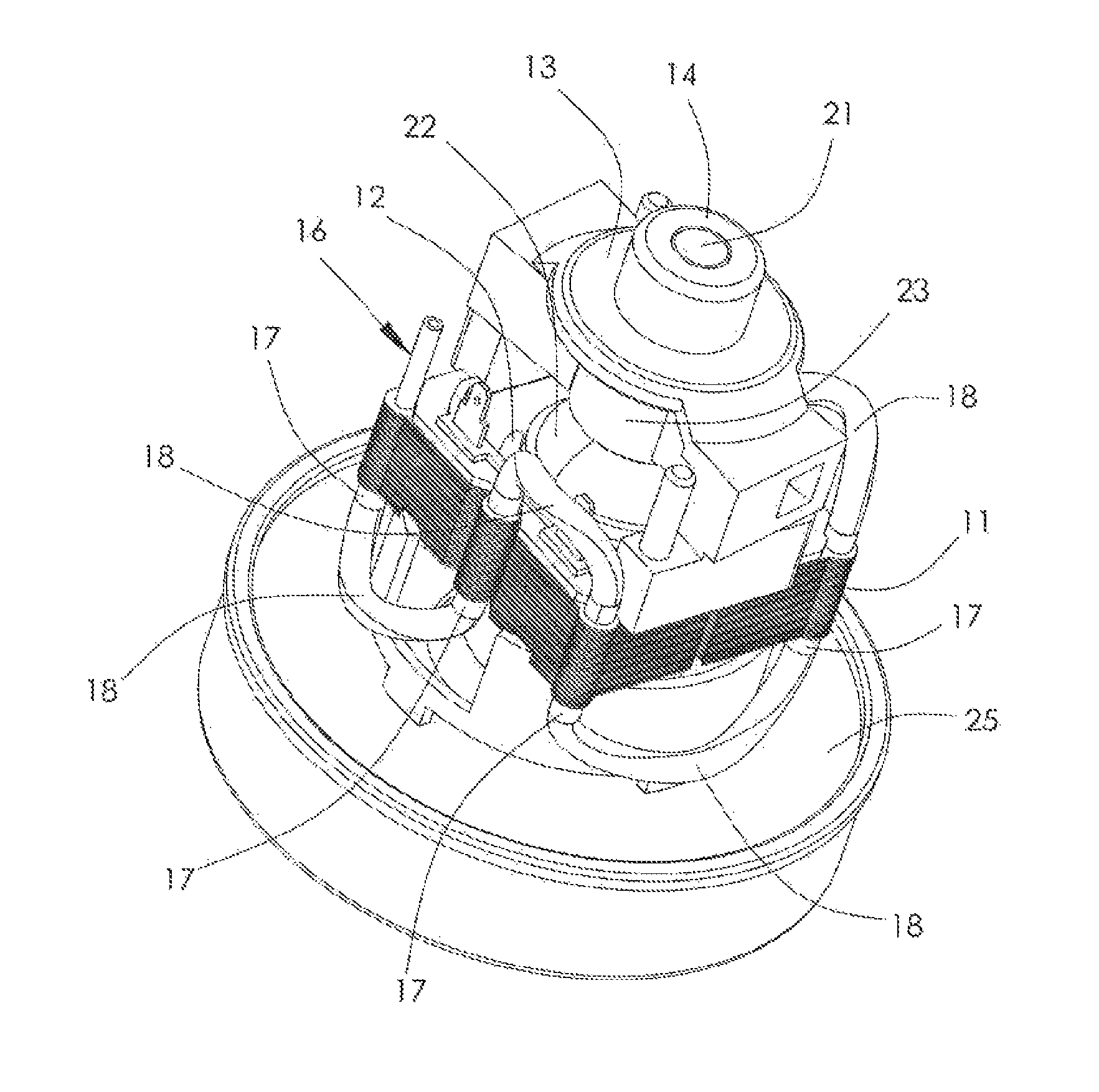
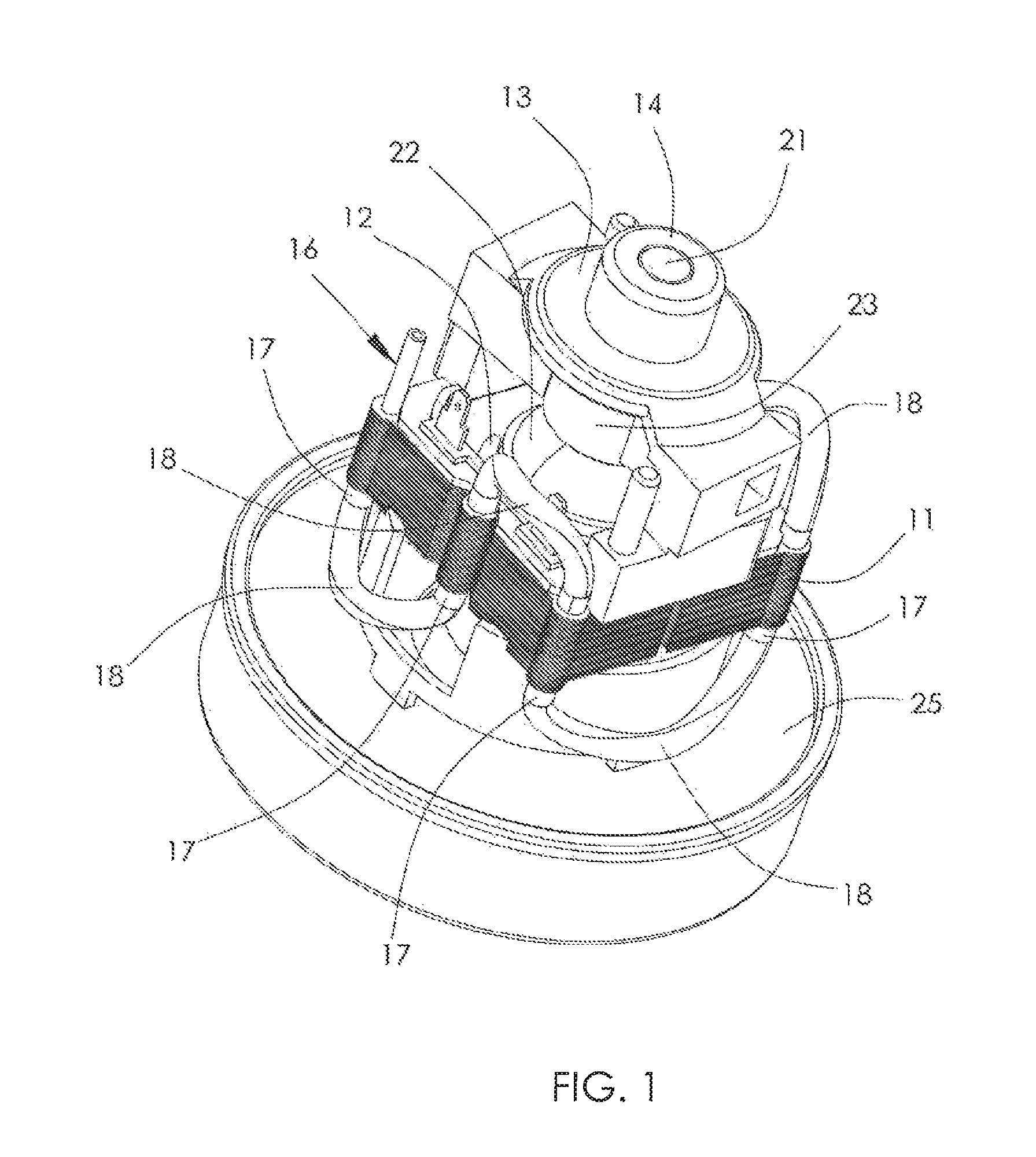
[0025]FIG. 1 illustrates a motor assembly according to the present invention. The motor assembly is a blower as used for example in a carpet cleaner or vacuum cleaner. The blower has an electric motor driving an impeller 25 which creates the vacuum for the appliance. The motor is a low power universal motor, preferably no more than 3,000 watts. Optionally, the motor is a fractional horsepower motor. The motor comprises a stator and a rotor 22 rotatably mounted to the stator. The stator comprises stator core 11, stator windings wound about teeth 12 of the stator core, brush gear disposed at one end of the stator core, and support members such as bearing brackets 13 mounted at respective ends of the stator core for rotatably supporting the rotor. The rotor comprises a shaft 21, rotor core mounted to the rotor shaft, a commutator 23 fixed to the rotor shaft adjacent to the rotor core, and rotor windings wound about teeth of the rotor core and electrically connected to segments of the c...

second embodiment

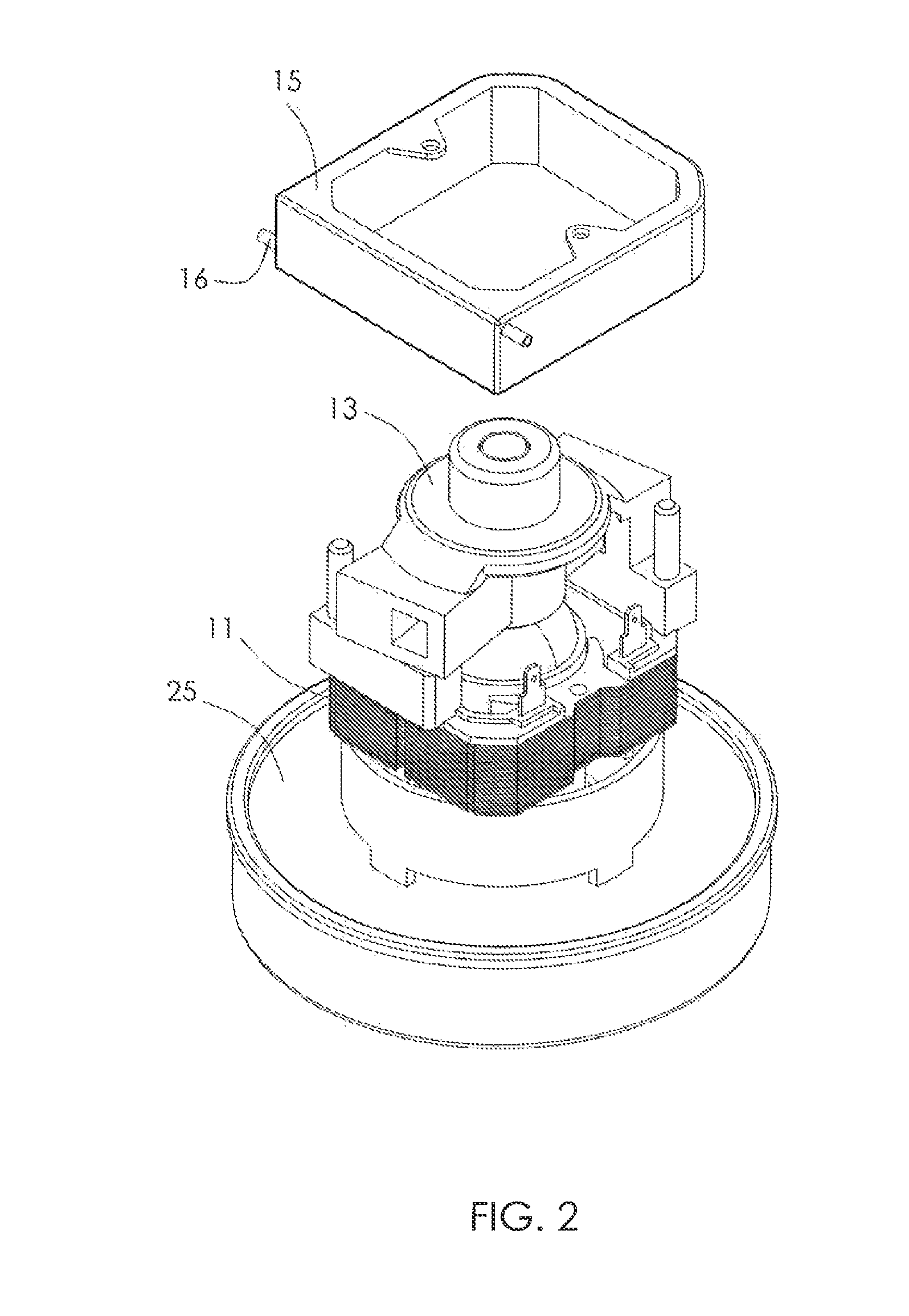
[0029]FIG. 2 and FIG. 3 illustrate another motor assembly according to the present invention. The motor assembly is shown fitted to a blower similar to the blower of FIG. 1. In this embodiment, the cooling pipe 16 is not embedded into the stator core 11. Instead, the cooling pipe 16 is disposed around the stator core 11 in a thermally conductive way, such that the cooling pipe is thermally coupled to the stator core. Specifically, the motor assembly comprises a thermally conductive ring member forming a cooling jacket 15 made of thermally conductive material such as aluminum. The cooling pipe 16 is spirally embedded inside the jacket 15. The cooling jacket 15 is mounted around the stator core 11, with thermally conductive silicone filled between the jacket 15 and the stator core 11, to improve the thermal connection between the stator core 11 and the jacket 15. The cooling pipe 16 is made of a thermal conductive material. The jacket 15 and the cooling pipe 16 are preferably formed a...


PUM


Abstract

A motor assembly, especially for home appliances such as a cleaner, has an electric motor and a cooling system. The motor may be a fractional horsepower universal motor with a stator and a rotor. The cooling system has a cooling pipe thermally coupled to an element of the stator, such as a core of the stator and providing a flow path for a liquid to cool the motor.

Description

CROSS REFERENCE TO RELATED APPLICATIONS[0001]This non-provisional patent application claims priority under 35 U.S.C. §119(a) from Patent Application No. 201010174457.6 filed in The People's Republic of China on May 11, 2010.FIELD OF THE INVENTION[0002]This invention relates to an electric motor assembly and in particular, to a water cooled electric motor for use in home appliances. The power of the motor is preferably not more than 3,000 watts. Preferably, the electric motor is rated as a fractional horsepower motor.BACKGROUND OF THE INVENTION[0003]Traditional small electric motors, especially fractional horsepower motors, are usually air cooled by an axial fan mounted on the rotor shaft to generate a flow of air. Because of the fan, the size of the motor is increased and the efficiency of the motor is decreased.[0004]Further more, in specified applications, there is not enough space for a channel or passage within the motor or stator for the air flow, preventing the heat from dissi...

Claims


Application Information

Patent Timeline
Patent Type & Authority Patents(United States)
IPC IPC(8): H02K9/19H02K9/20A47L7/00A47L11/34A47L11/40H02K1/20H02K9/22
CPCH02K9/22H02K9/19H02K1/20A47L11/34A47L11/4083H02K9/223H02K9/227H02K5/203
Inventor LAU, JAMES CHING SIKCAI, ZHAN
Owner JOHNSON ELECTRIC SA
Why Eureka
Try Eureka