
Coaxially arranged reduction gear assembly

a technology of worm gears and gear assemblies, which is applied in the direction of belts/chains/gearings, toothed gearings, and belts/chains/gearings, etc., can solve the problems of reducing the rotational accuracy of the system, reducing the efficiency of worm gears by design, and high cost and maintenance. , to achieve the effect of increasing the ratio, reducing the cost and improving the accuracy of rotation

Active Publication Date: 2014-09-09
AB SKF
View PDF13 Cites 1 Cited by
  • Summary
  • Abstract
  • Description
  • Claims
  • Application Information

AI Technical Summary

Benefits of technology

The coaxial reduction gear assembly is a special gear system that allows for precise rotation control, with gear ratios ranging from 40 to 1 to 250,000 to 1. The higher the ratio, the greater the accuracy. The assembly can easily compensate for tolerances in the gearing, and when used with an intelligent controller, it can provide the benefits of a stepper motor at a lower cost. It is also longer-lasting and requires less maintenance than other commonly used gear systems. The assembly is more efficient and can reduce power requirements, resulting in cost savings and increased longevity of the motor.

Problems solved by technology

The current solutions commonly incorporate stepper motors, which are expensive and are subjected to required maintenance.
Inclusion of an intermediary component, such as a belt or transmission, would reduce the rotational accuracy of the system.
Worm gears have limited efficiency by design.
The tolerances reduce the positional accuracy of the system.

Method used


Image

  • Coaxially arranged reduction gear assembly
  • Coaxially arranged reduction gear assembly
  • Coaxially arranged reduction gear assembly

Examples


Embodiment Construction

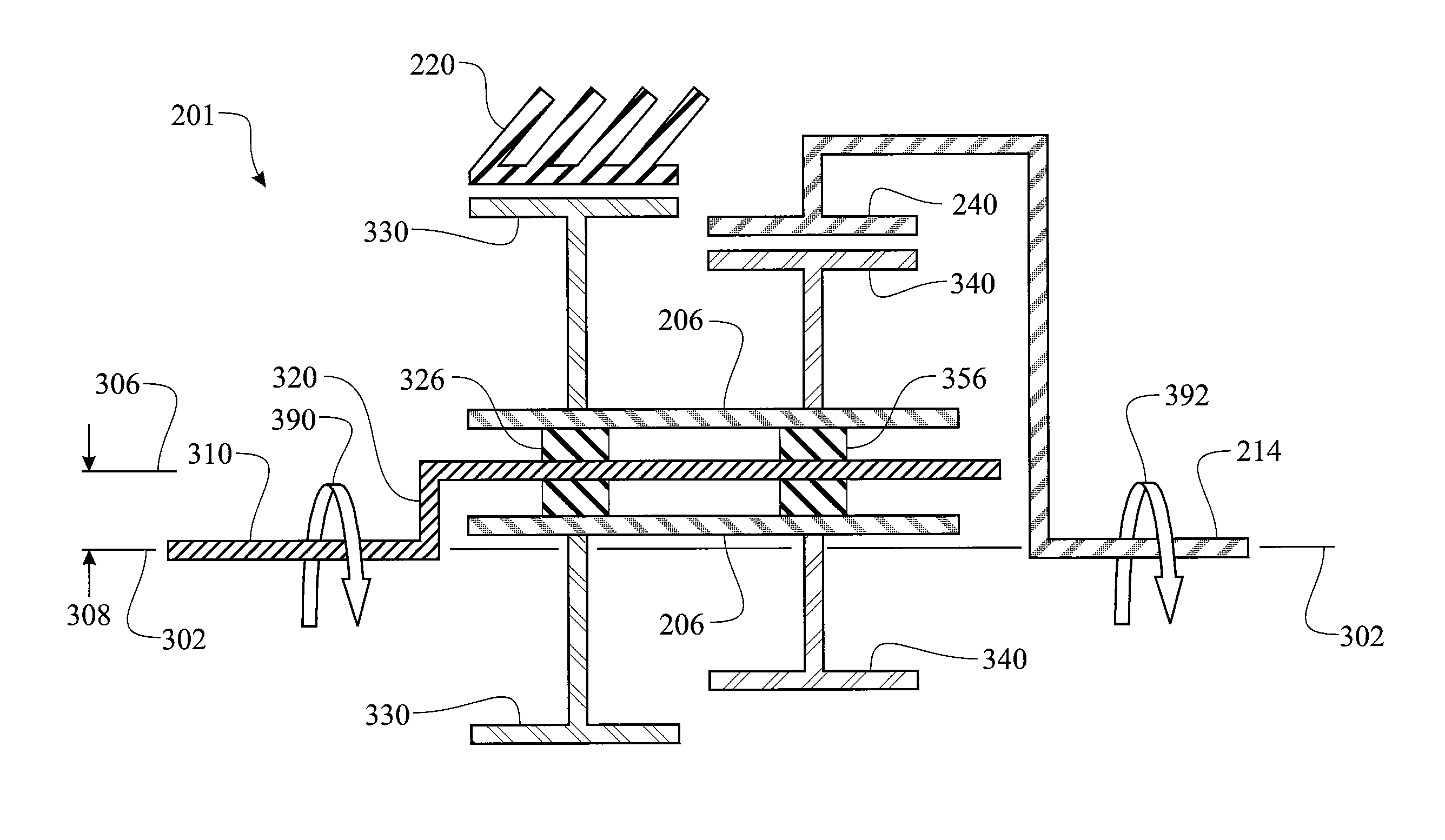
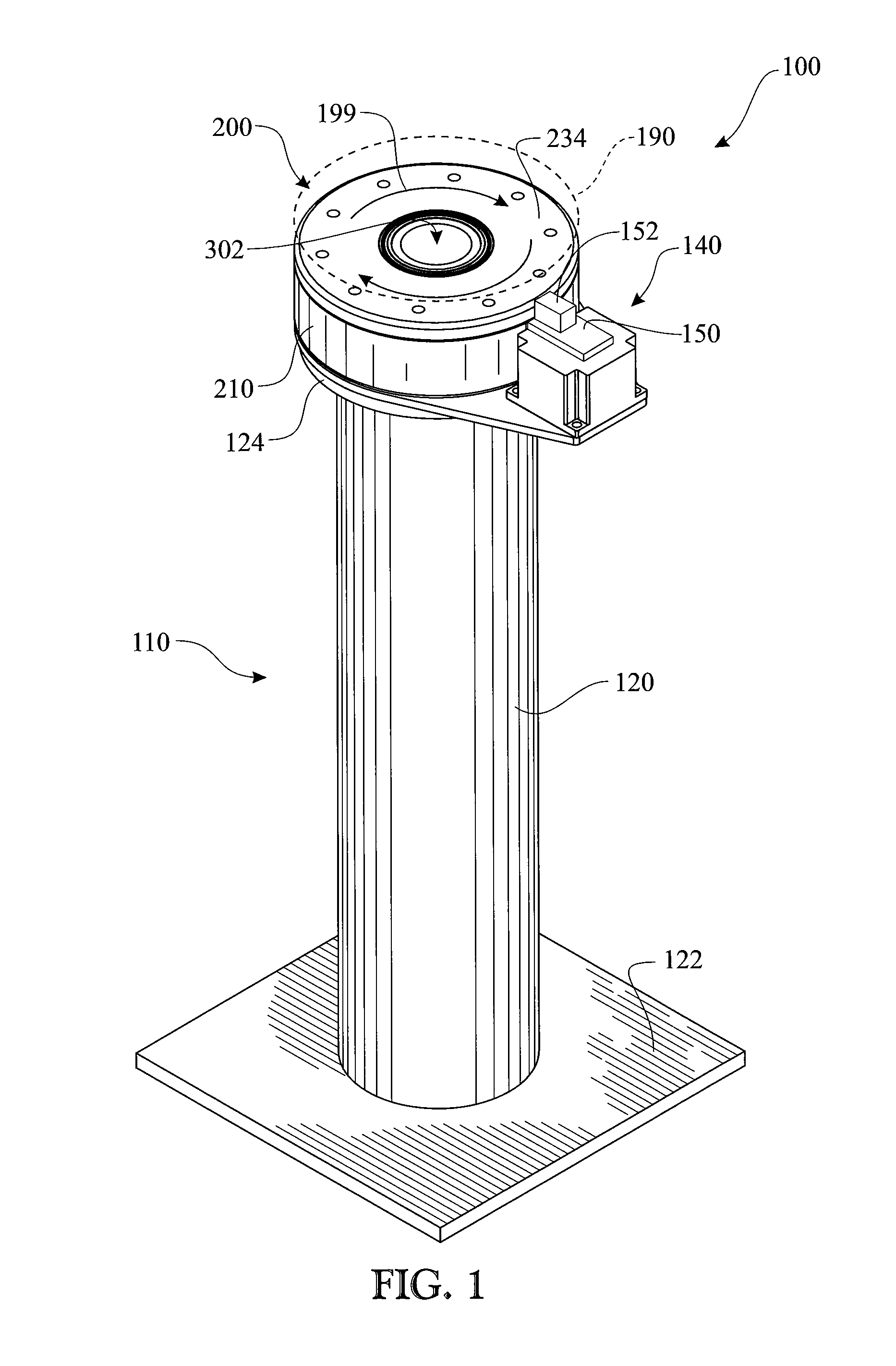
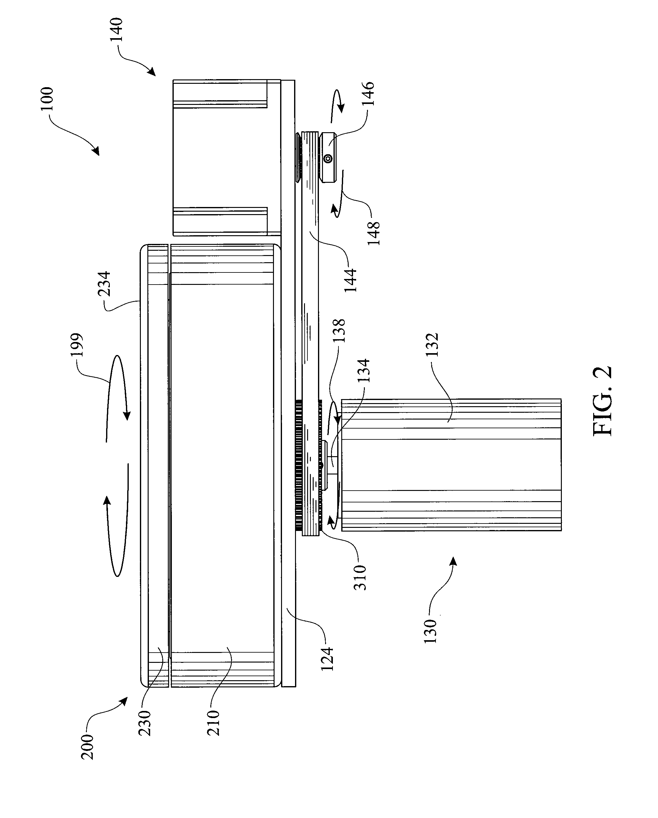
[0068]The following detailed description is merely exemplary in nature and is not intended to limit the described embodiments or the application and uses of the described embodiments. As used herein, the word “exemplary” or “illustrative” means “serving as an example, instance, or illustration.” Any implementation described herein as “exemplary” or “illustrative” is not necessarily to be construed as preferred or advantageous over other implementations. All of the implementations described below are exemplary implementations provided to enable persons skilled in the art to make or use the embodiments of the disclosure and are not intended to limit the scope of the disclosure, which is defined by the claims. For purposes of description herein, the terms “upper”, “lower”, “left”, “rear”, “right”, “front”, “vertical”, “horizontal”, and derivatives thereof shall relate to the invention as oriented in FIG. 1. Furthermore, there is no intention to be bound by any expressed or implied theo...


PUM


Abstract

A reduction gear assembly integrates a stationary section having a stationary internal gear configuration, an output section having an output internal gear configuration, an input shaft and planetary carrier comprising an input shaft having a shaft rotational axis and a planetary gear cam having a planetary gear rotational axis, wherein the shaft axis and cam axis are offset. A planetary gear comprising a planet wheel first stage and a planet wheel second stage is rotationally assembled to the planetary gear cam. The first stage planet wheel engages with the stationary gear. The second stage planet wheel engages with the output gear. Rotation of the input shaft rotates the planetary gear about a circular path. Engagement between the first stage and the stationary gear rotates the planetary gear. Second stage teeth engage with the output gear. Difference in first stage and second stage teeth counts causes rotation of the output section.

Description

BACKGROUND OF THE INVENTION[0001]1. Field of the Invention[0002]The present invention relates to a device providing functionality of a reduction gear for precise rotational motion of an object. More specifically, the device utilizing a planetary gear arrangement in conjunction with an offset gear configuration resulting in a high torque, highly accurate rotational motion.[0003]2. Discussion of the Related Art[0004]Many devices require precision rotational positioning. The current solutions commonly incorporate stepper motors, which are expensive and are subjected to required maintenance. Stepper motors are selected by the rotational accuracy and generated torsional force. The stepper motor design dictates the installation location. Inclusion of an intermediary component, such as a belt or transmission, would reduce the rotational accuracy of the system. Stepper motors, by the nature of their design, rotate in accordance with a pulsing pattern. Stepper motors require calibration and ...

Claims


Application Information

Patent Timeline
Patent Type & Authority Patents(United States)
IPC IPC(8): F16H1/32
CPCF16H1/321F16H2001/324F16H1/32
Inventor KULLIN, ARNE, LARS, JONAS
Owner AB SKF
Learn More