
Photo ionization detector for gas chromatography having two separately ionizing sources and methods of use

a technology of ionization detector and gas chromatography, which is applied in the direction of particle separator tube details, instruments, separation processes, etc., can solve the problems of not being found sufficiently successful for adoption, non-selective systems, and limiting the information which may be obtained from within the detector cell. , to achieve the effect of improving selectivity, reducing the photon energy, and increasing the photon energy

Active Publication Date: 2014-09-09
VALCO INSTRUMENT COMPANY INC
View PDF33 Cites 1 Cited by
  • Summary
  • Abstract
  • Description
  • Claims
  • Application Information

AI Technical Summary

Benefits of technology

The patent describes a photo ionization detector that uses two separate ionization sources and multiple collecting electrodes to improve selectivity. This allows the detector to confirm the identities of compounds based on their retention time. Additionally, the detector uses helium doped with other gases to provide a simultaneous emission profile and selectivity for different compound types. This eliminates the need for a second detector or division of the effluent from the gas chromatography column. The detector can also use different dopants for different compound types, making it highly versatile.

Problems solved by technology

Unfortunately, use of a single collecting electrode limits the information which may be obtained from within the detector cell.
Moreover, these systems are non-selective, as they respond to all compounds except the carrier gas.
While several methods for improving selectivity have been published, these have not been found sufficiently successful for adoption.
Splitting the eluent, however, can create difficulties in ensuring an equal division of compounds between the two associated detectors.
Moreover, the two detectors may produce differing results, such as by the result of contamination or deterioration of the detector components, which cannot be addressed by reference to a standard.

Method used


Image

  • Photo ionization detector for gas chromatography having two separately ionizing sources and methods of use
  • Photo ionization detector for gas chromatography having two separately ionizing sources and methods of use
  • Photo ionization detector for gas chromatography having two separately ionizing sources and methods of use

Examples


Embodiment Construction

[0024]The present photo ionization detector provides a detector body for dual discharge photo ionization detector with two or more collecting electrodes and a method of use for gas chromatography.

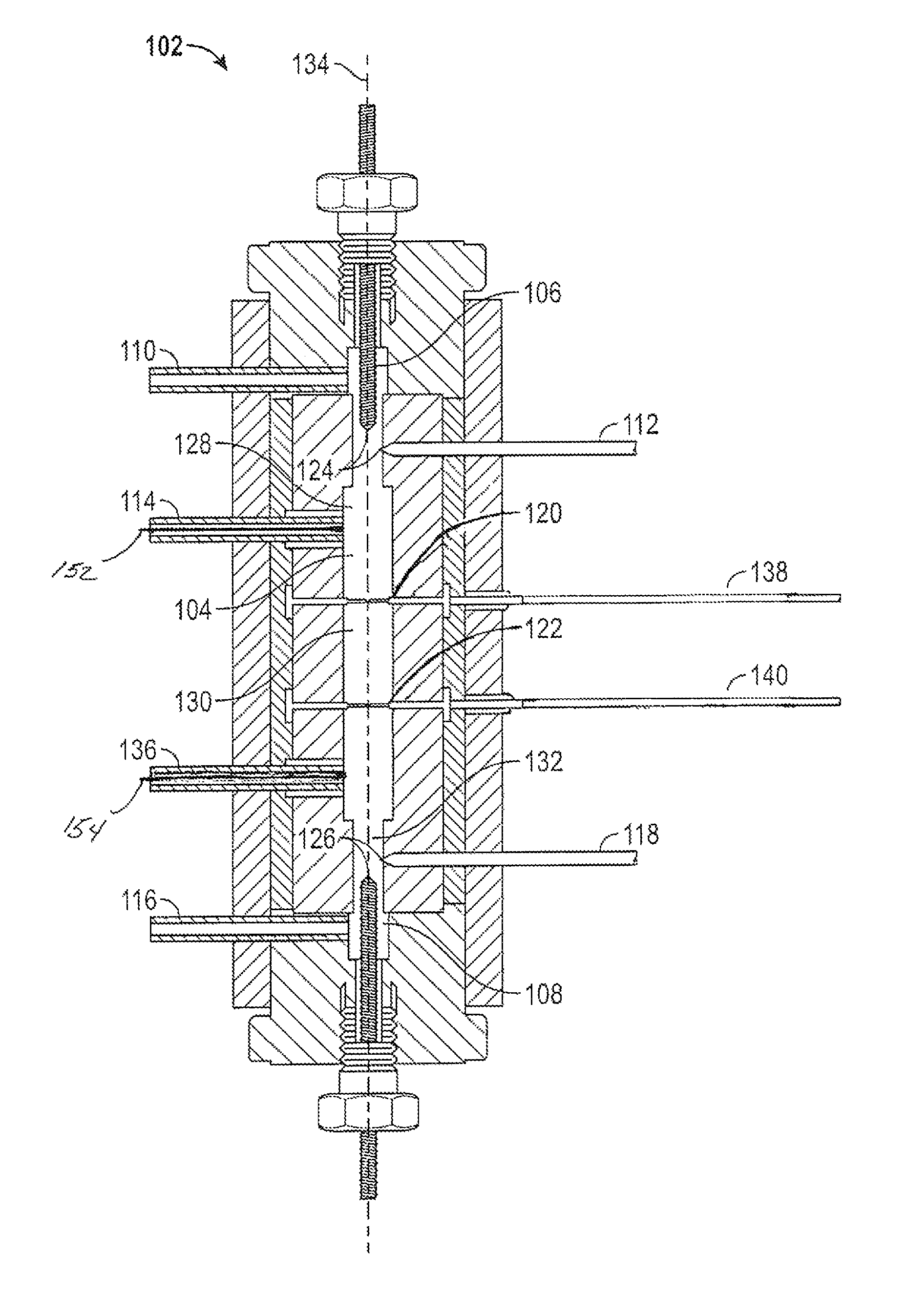
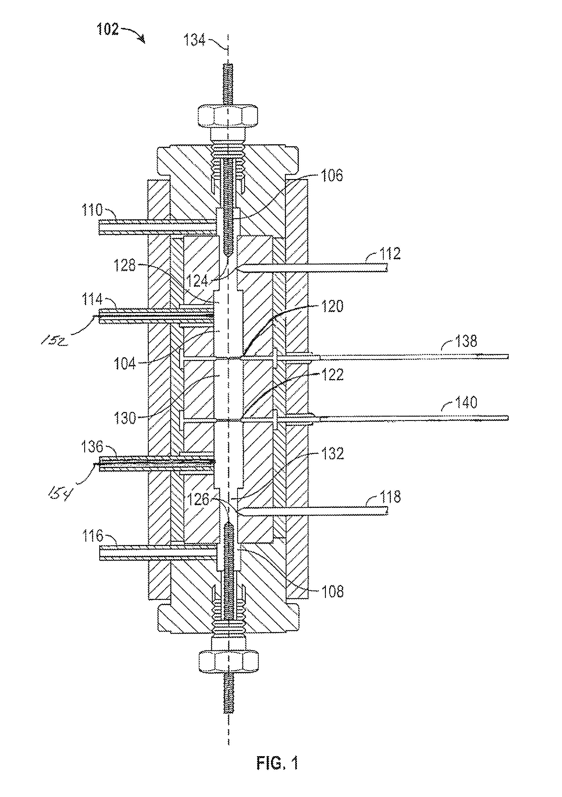
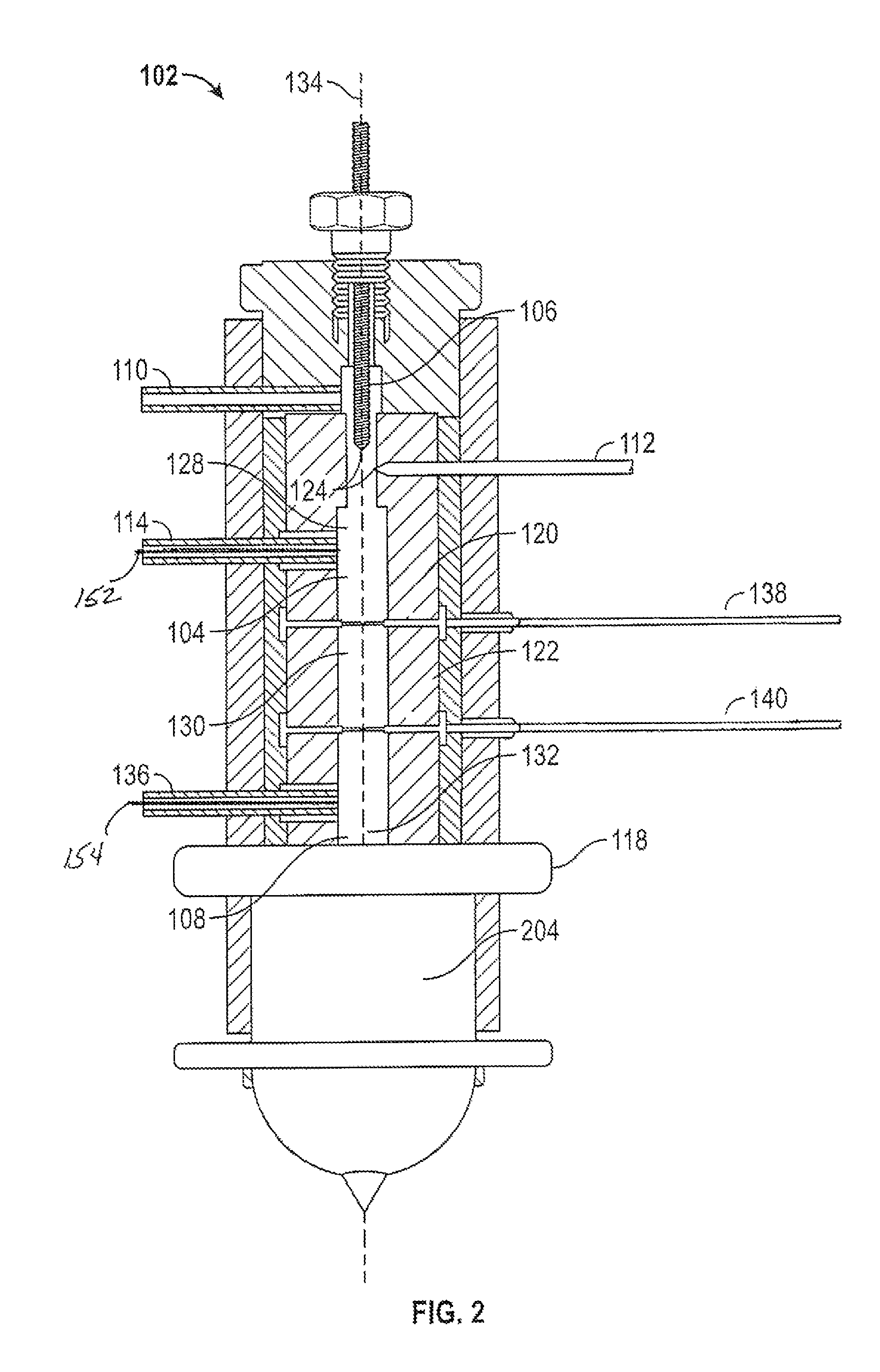
[0025]Referring to FIG. 1, an illustration of a detector body of the present photo ionization detector using pulsed discharge as the first and second ionization sources, the dual ionization source ionization detector body 102 includes an enclosed elongated chamber 104 having a chamber first end 106 and a chamber second end 108, a first ionization source 112, a second ionization source 118, a column gas inlet piping 114, a first collecting electrode 138 having a first collecting electrode end 120 which may be constructed to function as a combined bias / collecting electrode, and a second collecting electrode 140 having a second collecting electrode end 122 which may be constructed to function as a combined bias / collecting electrode, and an outlet piping 136 from the enclosed elongated chamber ...


PUM

PropertyMeasurementUnit
wavelengthaaaaaaaaaa
areaaaaaaaaaaa

Abstract

A detector for gas chromatography using two ionization sources within a single body to separately provide ionization energy to a column gas eluent to provide electrical discharge to two or more collecting electrodes provides improved selectivity and may be so used. Use is made of combined bias / collecting electrodes. The use of two ionization sources permits generation of two detector outputs from within a common body and of a common constituent flow. The ionization sources and any applicable discharge gas and dopant may be selected based on desired selectivity.

Description

CROSS-REFERENCE TO RELATED APPLICATIONS[0001]None.STATEMENT REGARDING FEDERALLY SPONSORED RESEARCH OR DEVELOPMENT[0002]Not Applicable.BACKGROUND OF THE INVENTION[0003]1. Field of Invention[0004]An improvement to ionization detectors for gas chromatography and methods of use is disclosed. More specifically, a detector for gas chromatography with two separate ionization sources within a single body to separately provide ionization energy to, via a discharge gas, permit ionization of a column gas eluent to provide electrical discharge to two or more collecting electrodes, which may be combined bias / collecting electrodes, and methods of use provides improved selectivity, is disclosed.[0005]2. Description of the Related Art[0006]Gas chromatograph systems used to detect the presence of specific compounds include the well-known use of ionization detectors. A sample is vaporized and introduced to the head of a gas chromatographic column, where it is transported through the column by the flo...

Claims


Application Information

Patent Timeline
Patent Type & Authority Patents(United States)
IPC IPC(8): G01N27/62H01J49/00G01N27/64G01N27/66G01N30/64H01J49/10
CPCG01N27/66H01J49/107G01N27/64G01N30/64G01N2030/642
Inventor STEARNS, STANLEY D.CAI, HUAMIN
Owner VALCO INSTRUMENT COMPANY INC
Learn More