Projector and image display method

a projector and image display technology, applied in the field of projectors, can solve the problems of reducing color reproducibility, reducing color reproducibility, and inability to acquire sufficient transmittance (or reflectance) for light having a wavelength in the neighborhood of the cutoff, so as to and reduce the amount of light emitted from the dichroic mirror

Active Publication Date: 2014-09-16
SHARP NEC DISPLAY SOLUTIONS LTD
View PDF27 Cites 8 Cited by
  • Summary
  • Abstract
  • Description
  • Claims
  • Application Information

AI Technical Summary

Benefits of technology

[0019]However, since the rising part of a curve (portion defining cutoff) indicating the spectral transmission characteristics of the dichroic mirror has a certain inclination, a sufficient transmittance (or reflectance) cannot be acquired for light having a wavelength in the neighborhood of the cutoff wavelength. For example, when the difference between the emission wavelength of the first green LED and the cutoff wavelength is small, a part of the first green optical beam emitted from the first green LED is transmitted through the dichroic mirror. Consequently, the reflected amount of the first green optical beam emitted from the dichroic mirror is reduced. When the difference between the emission wavelength of the second green LED and the cutoff wavelength is small, a part of the second green optical beam emitted from the second green LED is reflected or absorbed by the dichroic mirror. Consequently, the transmitted amount of the second green optical beam emitted from the dichroic mirror is reduced.
[0020]The problem in which a certain amount of light is reduced in the dichroic mirror can be solved by increasing the differences between the cutoff wavelength of the dichroic mirror and the emission wavelengths of the first and second green LEDs. In this case, however, since the difference between the emission wavelength of the first green LED and the emission wavelength of the second green LED is larger, the color purity of green included in a projected image drops, consequently reducing color reproducibility.
[0023]It is therefore an object of the present invention to provide a projector and an image display method that can solve both the problem in which a certain amount of light is reduced in the dichroic mirror and the problem in which the color purity of the green color included in the projected image is reduced and that can display a high-luminance image of high color reproducibility.Solution To Problem

Problems solved by technology

However, since the rising part of a curve (portion defining cutoff) indicating the spectral transmission characteristics of the dichroic mirror has a certain inclination, a sufficient transmittance (or reflectance) cannot be acquired for light having a wavelength in the neighborhood of the cutoff wavelength.
In this case, however, since the difference between the emission wavelength of the first green LED and the emission wavelength of the second green LED is larger, the color purity of green included in a projected image drops, consequently reducing color reproducibility.
In this case, however, the problem in which a certain amount of light is reduced in the dichroic mirror occurs.

Method used


Image

  • Projector and image display method
  • Projector and image display method
  • Projector and image display method

Examples


first embodiment

[0079](First Embodiment)

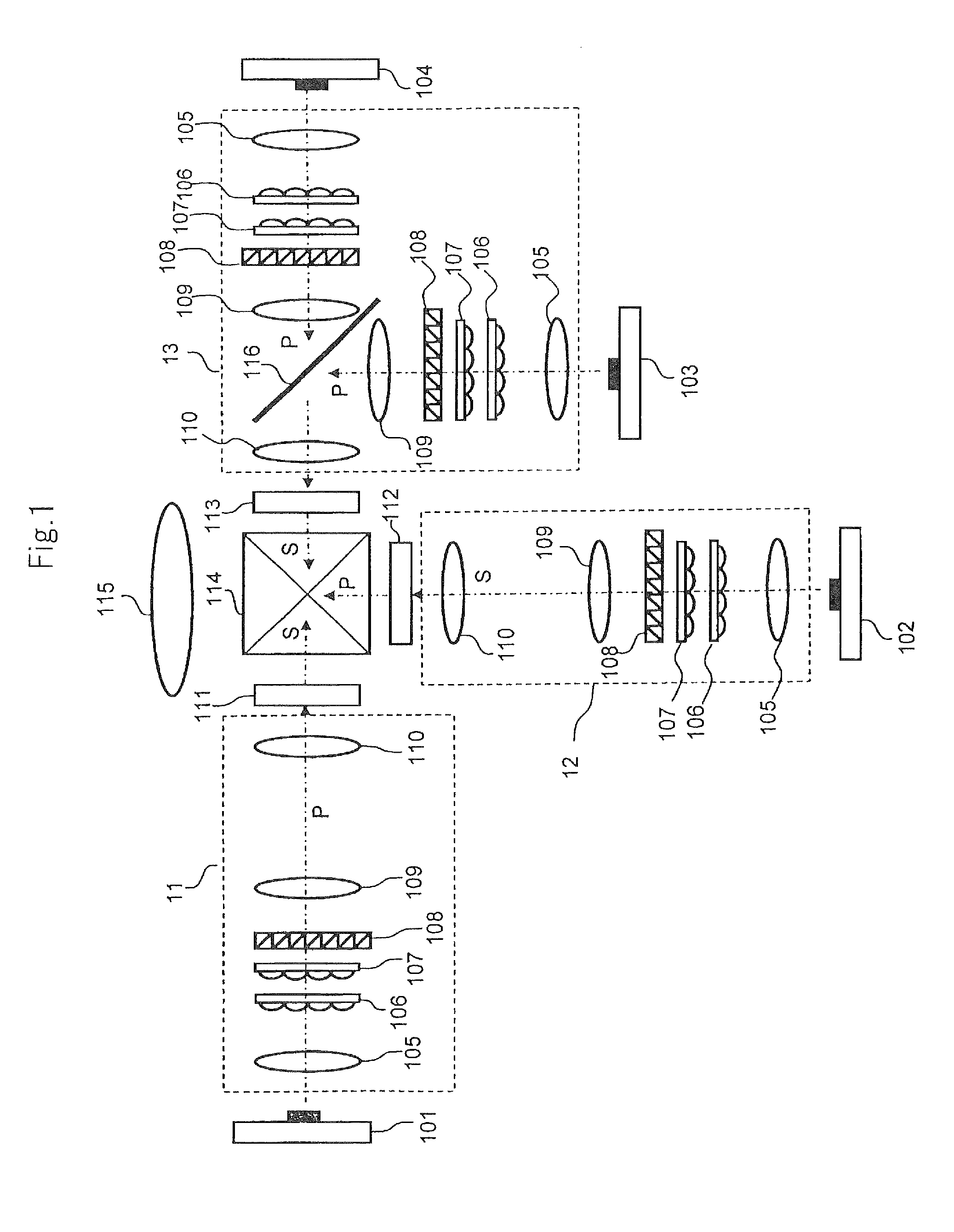
[0080]FIG. 1 is a schematic diagram showing the configuration of a projector according to the first embodiment of the present invention.

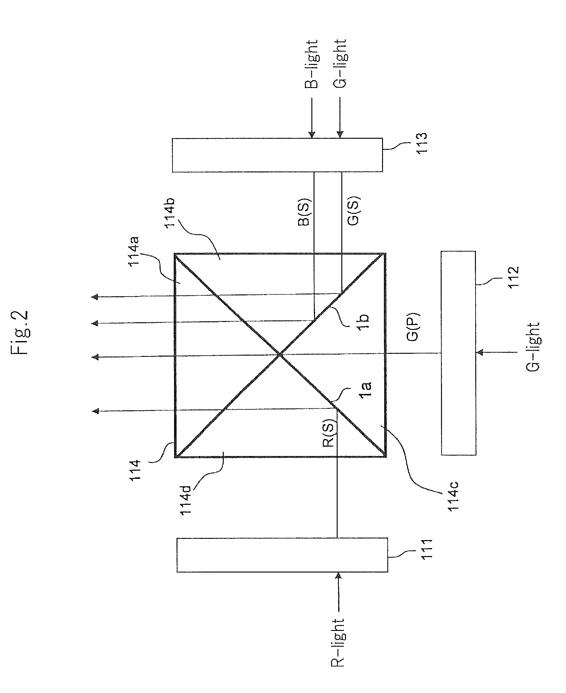
[0081]Referring to FIG. 1, the projector according to this embodiment includes red light source 101, green light sources 102 and 103, blue light source 104, lighting optical systems 11 to 13, liquid crystal panels 111 to 113, cross dichroic prism 114, and projection lens 115.

[0082]Red light source 101 that is a solid light source having a peak wavelength in a red wavelength band includes, for example, a LED or a semiconductor laser for emitting red light. Blue light source 104 that is a solid light source having a peak wavelength in a blue wavelength band includes, for example, a LED or a semiconductor laser for emitting blue light.

[0083]Each of green light sources 102 and 103 that is a solid light source having a peak wavelength in a green wavelength band includes, for example, a LED or a semiconductor laser for emitting gre...

second embodiment

[0170](Second Embodiment)

[0171]FIG. 8 is a schematic diagram showing the configuration of a projector according to the second embodiment of the present invention.

[0172]The projector according to this embodiment includes red light source 101, green light sources 102 and 103, blue light source 104, lighting optical systems 71 to 73, liquid crystal panels 111 to 113, cross dichroic prism 114, and projection lens 115.

[0173]Red light source 101, green light source 102, blue light source 104, liquid crystal panels 111 to 113, cross dichroic prism 114, and projection lens 115 are similar to those of the first embodiment.

[0174]Green light source 103, which is similar to that of the first embodiment, is used as a light source for liquid crystal panel 111.

[0175]A red optical beam emitted from red light source 101 and a green optical beam emitted from green light source 103 enter into lighting optical system 71 from different directions.

[0176]Lighting optical system 71 includes a first optical...

third embodiment

[0207](Third Embodiment)

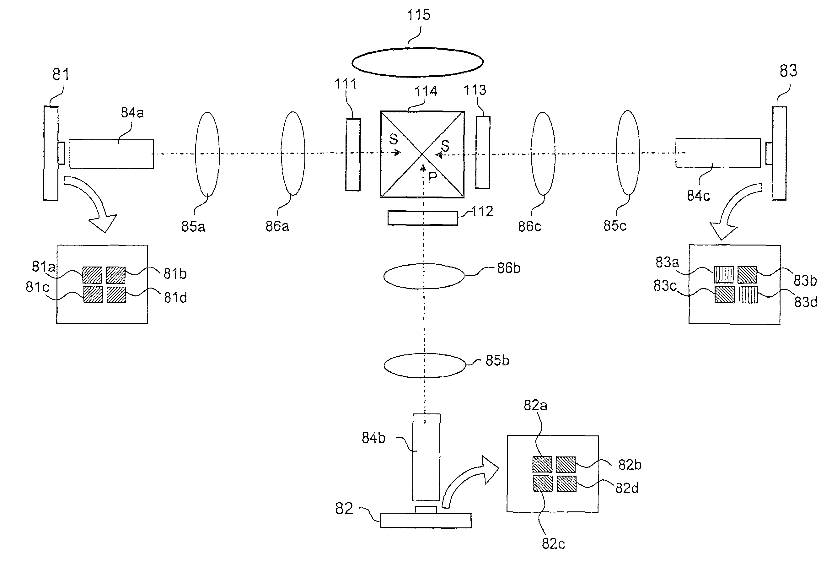
[0208]FIG. 12 is a schematic diagram showing the configuration of a projector according to the third embodiment of the present invention.

[0209]The projector according to this embodiment includes light sources 81 to 83, optical guiding units 84a to 84c, illumination lenses 85a to 85c and 86a to 86c, liquid crystal panels 111 to 113, cross dichroic prism 114, and projection lens 115.

[0210]Liquid crystal panels 111 to 113, cross dichroic prism 114, and projection lens 115 are similar to those of the first embodiment.

[0211]Light sources 81 to 83 are multichip type solid light sources each including a plurality of semiconductor chips. As the multichip type solid light sources, there are a LED and a semiconductor laser.

[0212]Light source 81 includes four chips 81a to 81d. Chips 81a to 81d, which can be individually controlled, output red light (P-polarized light). The area of the entire emission surface (rectangular region shown in FIG. 12) of chips 81a to 81d is a...


PUM


Abstract

A red image is displayed on liquid crystal panel (111) by lighting red light source (101) for a predetermined period. A green image is displayed on liquid crystal panel (112) by lighting green light source (102) for the predetermined period. A green image is displayed on liquid crystal panel (113) by lighting green light source (103) for the first of first and second periods provided by dividing the predetermined period with a predetermined ratio. A blue image is displayed on liquid crystal panel (113) by lighting blue light source (104) for the second period.

Description

TECHNICAL FIELD[0001]The present invention relates to a projector, and more particularly to a 3-plate projector that includes three display elements and projects a color image formed by synthesizing red, green, and blue images respectively displayed on the display elements.BACKGROUND ART[0002]Generally, the projector is under restrictions of etendue determined by the light emission area and the divergence angle of a light source. The etendue restricts how much light from the light source can be used as projected light.[0003]In other words, in the projector, if the value that is the product of the area of the light source and the angle of divergence is not made less than or equal to the value of the product of the area of a display element (e.g., liquid crystal panel) and the acceptance angle (solid angle) that is determined by the f-number of the projection lens, the light from the light source cannot be efficiently used as projected light. Thus, for example, even if a number of LED...

Claims


Application Information

Patent Timeline
Patent Type & Authority Patents(United States)
IPC IPC(8): G03B21/00
CPCH04N9/3182G03B21/14H04N9/12G03B33/12G03B21/2033H04N9/3167H04N9/3105H04N9/3114
Inventor KATOU, ATSUSHI
Owner SHARP NEC DISPLAY SOLUTIONS LTD
Why Eureka
Try Eureka