Ion manipulation device

a technology of ion optics and ion beams, applied in the direction of instruments, particle separator tube details, separation processes, etc., can solve the problems of increasing the cost and/or inefficiency of conventional instrument designs and ion optic approaches, increasing the cost of ion optic approaches, and new opportunities can become limited, so as to reduce the possibility of trapping effect, improve performance, and reduce the effect of m/z rang

Active Publication Date: 2014-09-16
BATTELLE MEMORIAL INST
View PDF20 Cites 92 Cited by
  • Summary
  • Abstract
  • Description
  • Claims
  • Application Information

AI Technical Summary

Benefits of technology

[0034]In another embodiment of the present invention, each central or inner electrode is replaced by two or more electrodes with adjacent electrodes having different phase of the RF applied such that the traps formed for ions close to one of the surfaces are substantially reduced, resulting in improved performance such as a reduction of possible trapping effects or reduction in the m / z range that can be transmitted, particularly when ion currents near the upper limit are being transmitted.

Problems solved by technology

As the roles for mass spectrometry and other technologies that involve the use, manipulation or analysis of ions continue to expand, new opportunities can become limited by approaches currently used for extended sequences of ion manipulations, including their transport through regions of elevated pressure, reaction (both ion-molecule and ion-ion), and ion mobility separations.
As such manipulations become more sophisticated, conventional instrument designs and ion optic approaches become increasingly impractical, expensive and / or inefficient.

Method used


Image

  • Ion manipulation device
  • Ion manipulation device
  • Ion manipulation device

Examples


example

[0080]The following examples serve to illustrate certain embodiments and aspects of the present invention and are not to be construed as limiting the scope thereof.

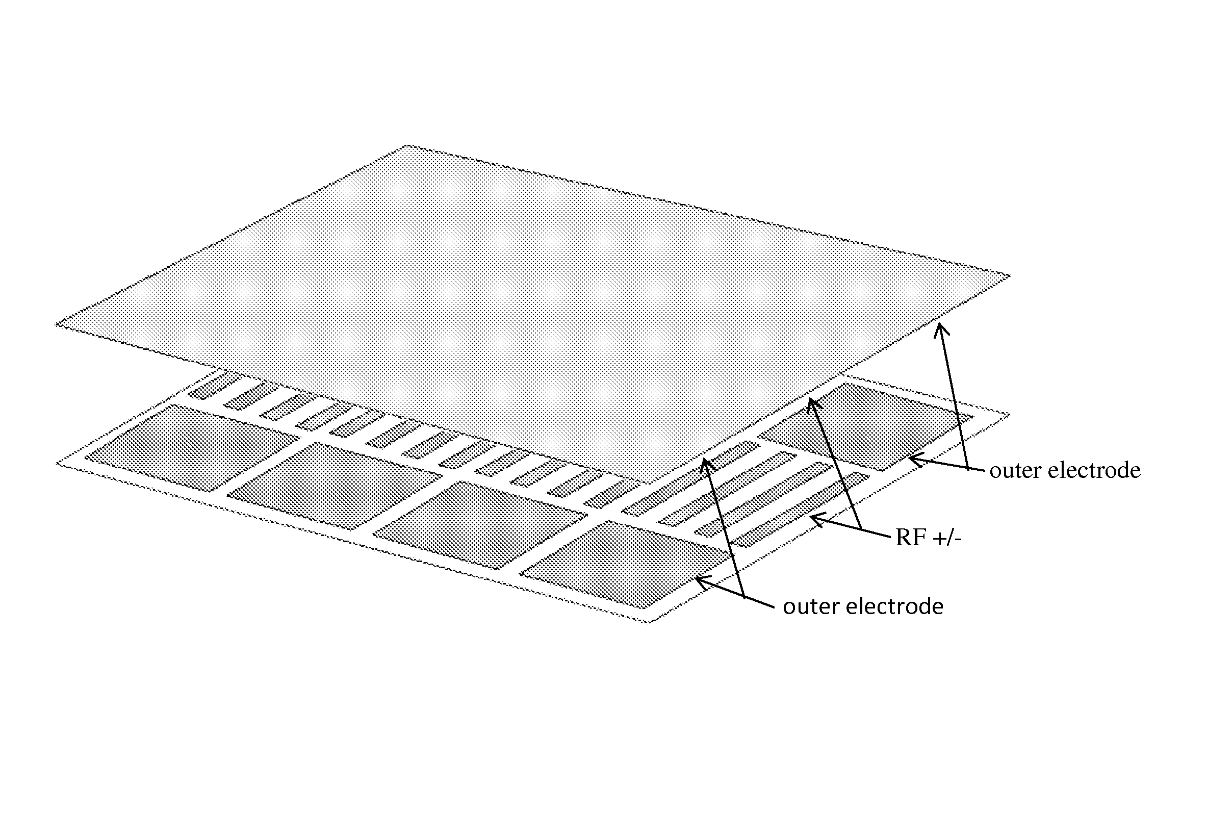
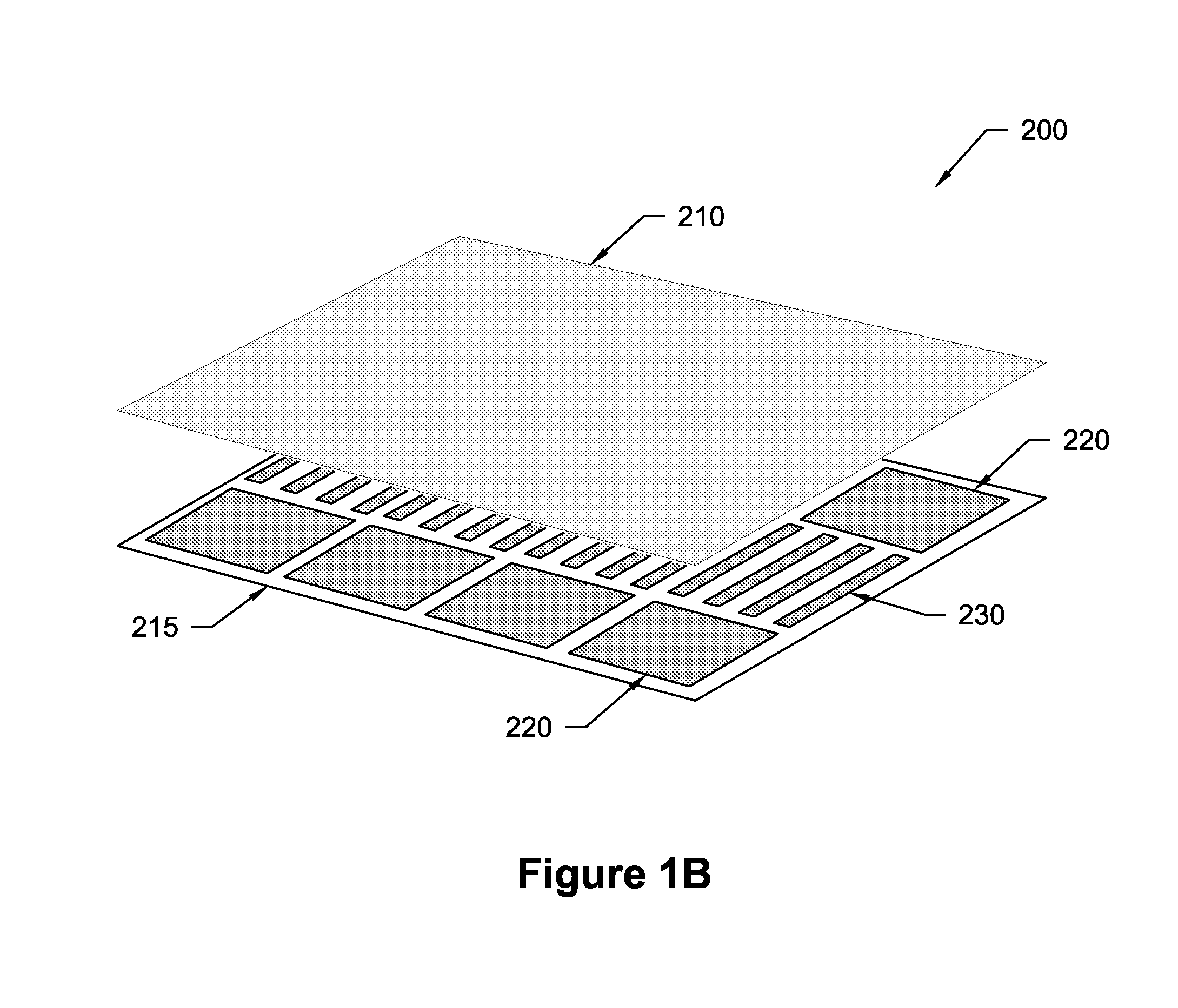
[0081]A device, as shown in FIG. 1B, was used to manipulate ions injected from an external ESI source. Simulations were performed to refine the design of the device; e.g. electrode sizes and spacing between the planar surfaces were adjusted. Boards were fabricated with electrode regions to test capabilities that included efficient ion transportation, ion mobility separations, ion trapping, and ion switching between alternative corridors or paths.

[0082]In one test, ions were introduced from the external ESI source and injected into one of the ion corridors at a pressure of ˜4 torr. RF frequencies of approximately 1.4 MHz and 140 Vp-p were applied to create repulsive fields to confine ions within the ion corridors between the opposing board surfaces. The RF fields were combined with DC for further confinement to the corrido...


PUM


Abstract

An ion manipulation method and device is disclosed. The device includes a pair of substantially parallel surfaces. An array of inner electrodes is contained within, and extends substantially along the length of, each parallel surface. The device includes a first outer array of electrodes and a second outer array of electrodes. Each outer array of electrodes is positioned on either side of the inner electrodes, and is contained within and extends substantially along the length of each parallel surface. A DC voltage is applied to the first and second outer array of electrodes. A RF voltage, with a superimposed electric field, is applied to the inner electrodes by applying the DC voltages to each electrode. Ions either move between the parallel surfaces within an ion confinement area or along paths in the direction of the electric field, or can be trapped in the ion confinement area.

Description

CROSS-REFERENCE TO RELATED APPLICATIONS[0001]This application claims priority to U.S. Provisional Application Ser. No. 61 / 809,660, filed Apr. 8, 2013, titled “ION MANIPULATION DEVICE,” hereby incorporated by reference in its entirety for all of its teachings.STATEMENT REGARDING FEDERALLY SPONSORED RESEARCH OR DEVELOPMENT[0002]The invention was made with Government support under Contract DE-AC05-76RLO1830, awarded by the U.S. Department of Energy. The Government has certain rights in the invention.TECHNICAL FIELD[0003]This invention relates to ion manipulations in gases. More specifically, this invention relates to the use of RF and / or DC fields to manipulate ions through electrodes, and building complex sequences of such manipulations in devices that include one or more such surfaces and structures built upon the surfaces.BACKGROUND OF THE INVENTION[0004]As the roles for mass spectrometry and other technologies that involve the use, manipulation or analysis of ions continue to expan...

Claims


Application Information

Patent Timeline
Patent Type & Authority Patents(United States)
IPC IPC(8): B01D59/44H01J49/06
CPCH01J49/06H01J49/062G01N27/622
Inventor ANDERSON, GORDON A.SMITH, RICHARD D.IBRAHIM, YEHIA M.BAKER, ERIN M.
Owner BATTELLE MEMORIAL INST
Why Eureka
Try Eureka