
Squirrel-cage rotor

a rotor and cage technology, applied in the direction of synchronous motors, dynamo-electric machines, electrical apparatus, etc., can solve the problems of impaired electrical transition conductivity between the short-circuiting rings and the rotor bars, high requirements for die-casting molds, and complex copper die-casting process, so as to achieve good electrical efficiency and strengthen the bond between the conductors and the short-circuiting rings

Active Publication Date: 2014-09-16
SIEMENS AG
View PDF16 Cites 15 Cited by
  • Summary
  • Abstract
  • Description
  • Claims
  • Application Information

AI Technical Summary

Benefits of technology

The invention provides a squirrel-cage rotor for an asynchronous machine that has good electrical efficiency and is resilient to thermal stresses and high rotational speeds. The rotor has slots filled with a first material, and short-circuited bars that are fixed outstandingly in the slots. The short-circuited bars improve the starting response of the asynchronous machine. The coating material used is a first material, which binds to the conductors by strong bonding forces. An oxide layer is removed from the conductors by chemical pretreatment before coating, reducing the transition resistance between the two materials. The coating material is further strengthened by interlocking means in the end regions of the conductors. The invention allows for a simple and efficient design of the squirrel-cage rotor with good electrical efficiency and resilience.

Problems solved by technology

As a result, the copper bars can break away from the die-cast aluminum material of the short-circuiting rings, as a result of which finally the electrical transition conductivity between the short-circuiting rings and the rotor bars is impaired.
However, the copper die-casting process is very complex and places stringent requirements on the die-casting mold, since copper has to be heated to temperatures of above 1000° C. for the die-casting process.

Method used


Image

  • Squirrel-cage rotor
  • Squirrel-cage rotor
  • Squirrel-cage rotor

Examples


Embodiment Construction

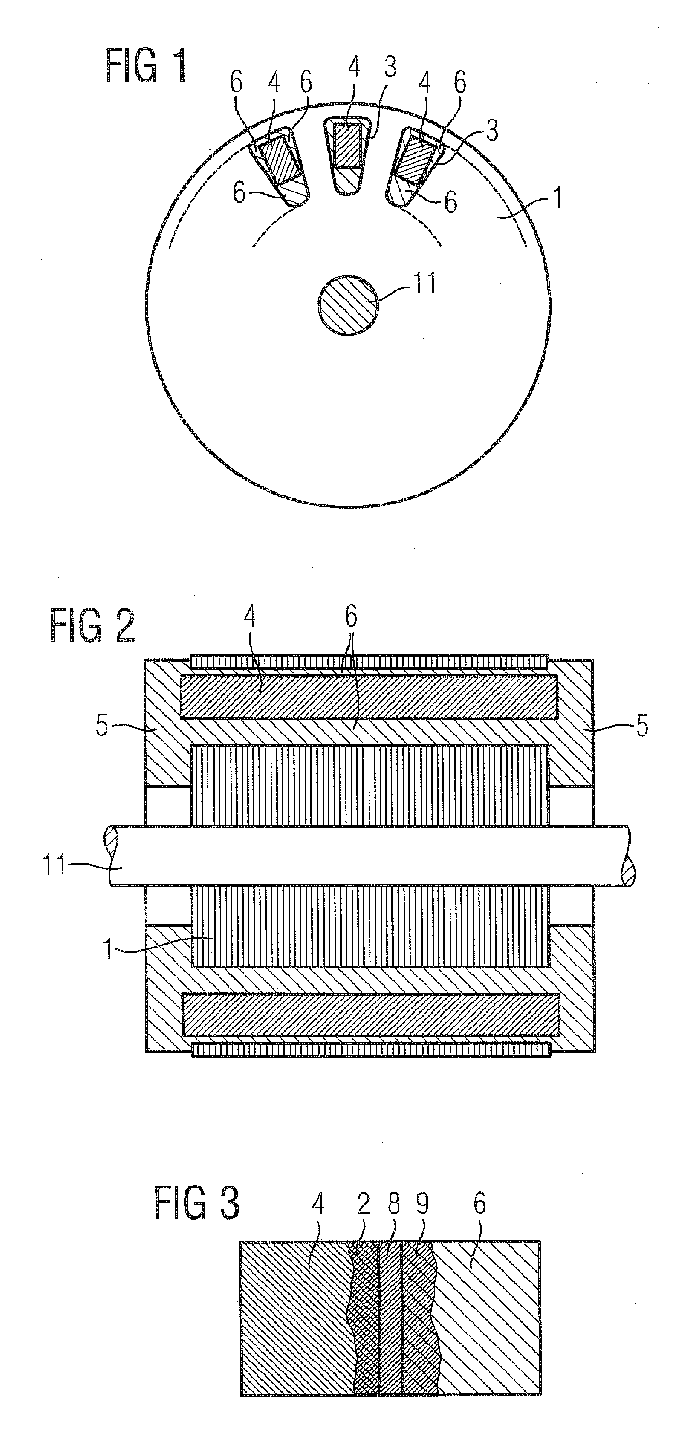
[0039]FIG. 1 shows an embodiment of a squirrel-cage rotor of an asynchronous machine in a hybrid construction. This figure illustrates a laminated rotor core 1 of the asynchronous machine, which is shrunk onto a shaft 11. During the production of the squirrel-cage rotor, conductors 4, which are preferably made of copper, are firstly pushed into slots 3 of the laminated rotor core 1. As can be seen, the cross section of the conductors 4 is smaller than the cross-sectional area of the slots 3. Therefore, a residual cross section of the slot 3 remains free after the conductors 4 (in the form of copper bars) have been inserted.

[0040]In order to produce the short-circuited rotor, in the next step a die-casting process is employed. In this process, short-circuiting rings in contact at the end faces with the copper bars are produced, and at the same time the still free space of the slots 3 is filled with a melt. Aluminum bar parts 6, which fix the copper bars in their position and adjoin t...


PUM


Abstract

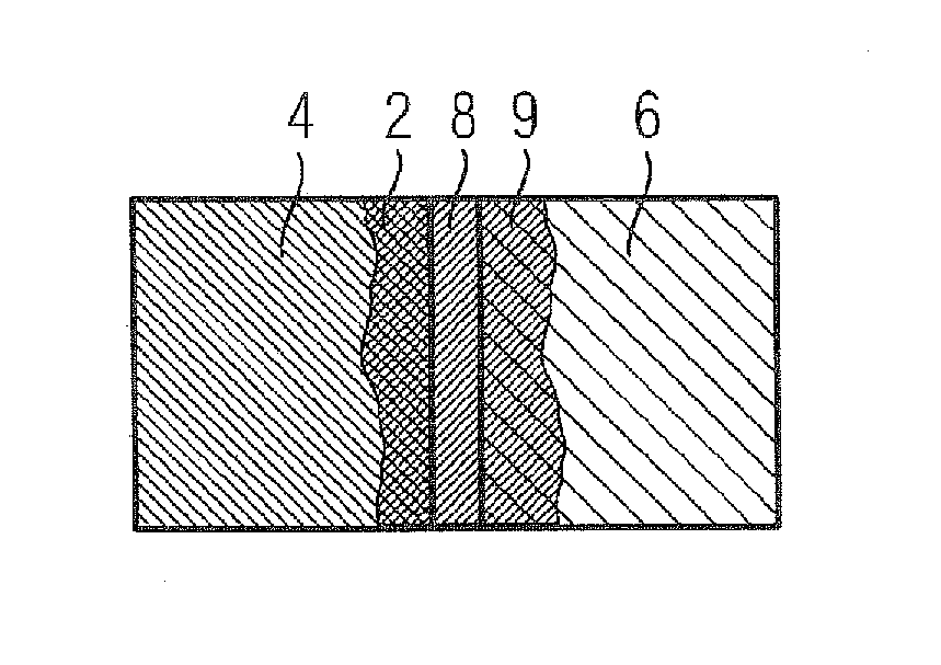
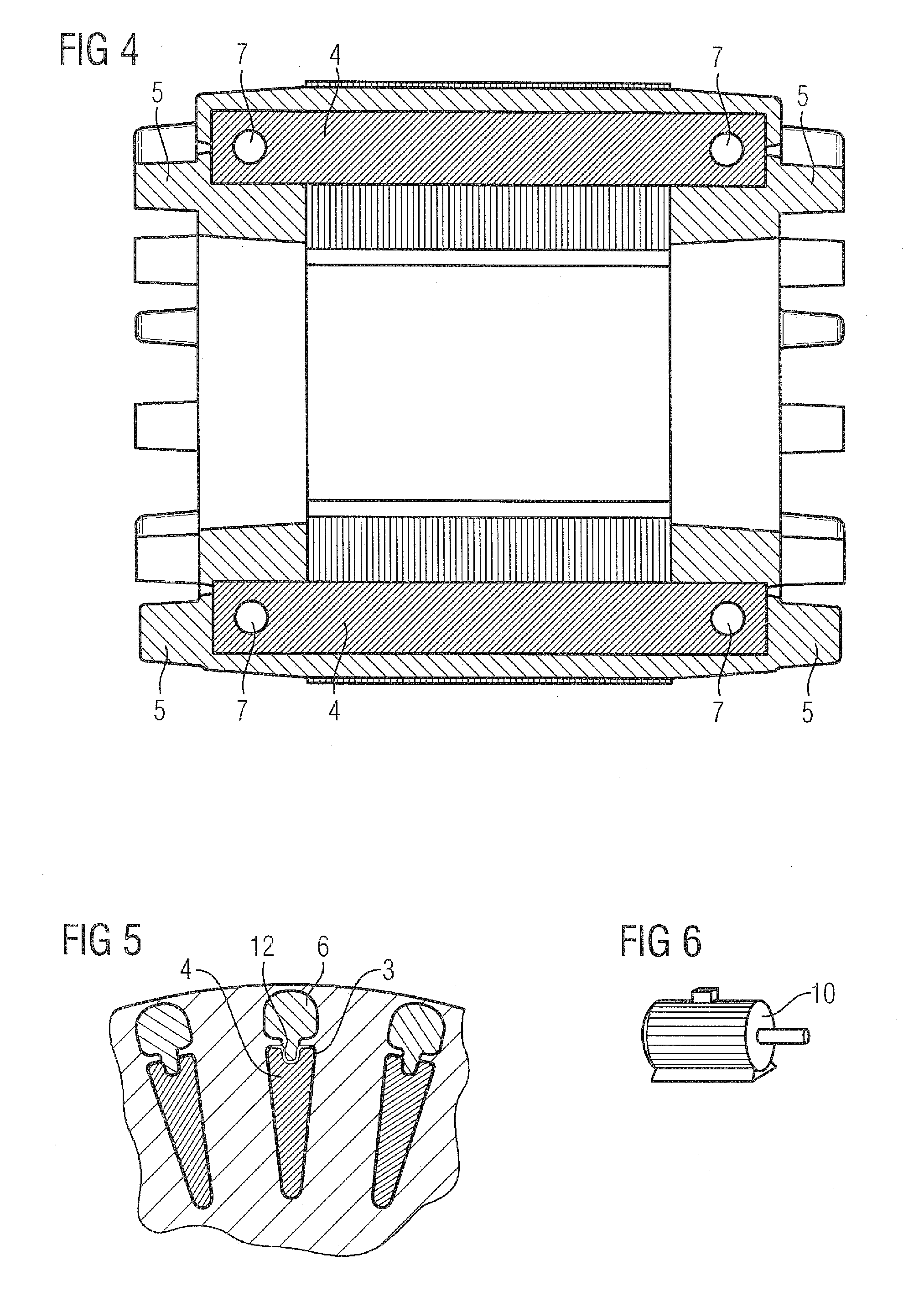
The invention relates to a squirrel-cage rotor for an asynchronous machine. In order to increase the electrical efficiency for a cage rotor composed of two materials, the cage rotor comprises a rotor core (1) having grooves (3), end rings (5) of a first material that are cast onto the rotor core on the end face, and conductors (4) that are arranged in the grooves and that are made of a second material that has an electric conductivity that is higher than the electric conductivity of the first material, wherein the conductors (4) comprise a coating (8) made of a coating material on the surface of the conductors, wherein the coating adjoins the second material of the conductors (4) by means of a first alloy layer (2) made of the second material and the coating material and adjoins the cast first material by means of a second alloy layer (9); made of the first material and the coating material.

Description

CROSS-REFERENCES TO RELATED APPLICATIONS[0001]This application is the U.S. National Stage of International Application No. PCT / EP2010 / 051441, filed Feb. 5, 2010, which designated the United States and has been published as International Publication No. WO 2010 / 100007 A1 and which claims the priority of German Patent Application, Serial No. 10 2009 008 440.1, filed Feb. 11, 2009, pursuant to 35 U.S.C. 119(a)-(d).BACKGROUND OF THE INVENTION[0002]The invention relates to a squirrel-cage rotor for an asynchronous machine. Furthermore, the invention relates to a process for producing a squirrel-cage rotor.[0003]Such a squirrel-cage rotor is known from DE 43 08 683 A1. This rotor comprises a laminated core with slots, into which short-circuited bars made of copper are initially pushed in. At the end faces, the copper bars are bonded to one another by short-circuiting rings. These short-circuiting rings are produced from aluminum by a die-casting process. As the short-circuiting rings are ...

Claims


Application Information

Patent Timeline
IPC IPC(8): H02K17/16H02K17/18H02K17/20
CPCH02K17/165H02K17/205Y10T29/49012H02K17/20
Inventor BUTTNER, KLAUSKURTH, JENSMULLER, MICHAELWOHNER, NORBERT
Owner SIEMENS AG
Learn More