
Differential serial interface for supporting a plurality of differential serial interface standards

a serial interface and differential technology, applied in the direction of transmission, modulated carrier systems, electrical devices, etc., can solve the problem that video interface transceivers are limited to supporting generally only one or two different video interface standards

Active Publication Date: 2014-09-16
TERADICI CORP
View PDF8 Cites 53 Cited by
  • Summary
  • Abstract
  • Description
  • Claims
  • Application Information

AI Technical Summary

Benefits of technology

The patent is for a circuit that doubles the capacity of an active capacitor, which is a type of electronic component. This circuit has various benefits and innovative features. It can help improve the performance and reliability of electronic devices.

Problems solved by technology

Such video interface transceivers are limited to supporting generally only one or two different video interface standards.

Method used


Image

  • Differential serial interface for supporting a plurality of differential serial interface standards
  • Differential serial interface for supporting a plurality of differential serial interface standards
  • Differential serial interface for supporting a plurality of differential serial interface standards

Examples


Embodiment Construction

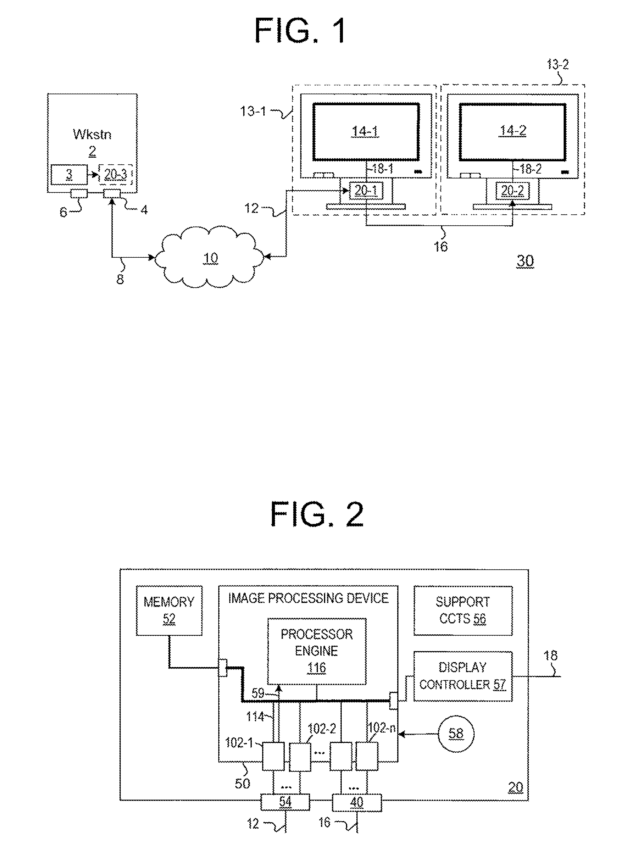
[0032]FIG. 1 is a block diagram of a networked computing system 39 in accordance with one or more embodiments of the present invention. The networked computing system 30 (“system 30”) comprises a workstation 2 having a Graphics Processing Unit (GPU) 3 and network interface 4 coupled, via a network cable 8, to a network 10. The workstation 2 further comprises a display interface 6 for connecting the workstation 2 to a local display device, such as a computer monitor. The workstation 2 is coupled via the network 10 to a client terminal 13-1. The client terminal 13-1 is coupled to the network 10 by a network cable 12, and is further coupled to a second client terminal 13-2 by a display cable 16. The client terminals 13-1 and 13-2 may collectively be referred to as client terminals 13, of which, in the embodiment of system 30, client terminal 13-1 functions as a primary display and client terminal 13-2 functions as a secondary display of a dual display configuration. This figure only po...


PUM


Abstract

An active capacitor multiplying circuit that in one embodiment comprises (i) a clock synthesis loop filter of at least second order comprising a series combination of a first resistor and a first capacitor, wherein the series combination is coupled between a first charge pump interface and ground, wherein the clock synthesis loop filter further comprises a second capacitor coupled between the first charge pump interface and the ground; (ii) a capacitor multiplying loop filter comprising a second capacitor coupled between a second charge pump interface and the ground, wherein the capacitor multiplying loop filter further comprises a second resistor coupled to the second charge pump interface and the second charge pump interface is coupled to the first charge pump interface; and (iii) an operational amplifier, driven by the first capacitor, for driving the second resistor, wherein a voltage presented at the first charge pump interface drives a voltage controlled oscillator.

Description

CROSS-REFERENCE TO RELATED APPLICATIONS[0001]This application is a continuation of co-pending U.S. patent application Ser. No. 13 / 595,646, entitled “Differential Serial Interface for Supporting a Plurality of Differential Serial Interface Standards” and filed Aug. 27, 2012, which is herein incorporated in its entirety by reference.BACKGROUND OF THE INVENTION[0002]1. Field of the Invention[0003]The invention relates generally to a direction-selectable differential high-speed serial interface with shared transmitter and receiver interface that support multiple video protocols (e.g., Display Port (DP), Digital Video Interface (DVI), High-Definition Multimedia Interface (HDMI), Low-voltage differential signaling (LVDS), and other protocols (e.g., Peripheral Component Interconnect Express (PCIe)).[0004]2. Description of the Related Art[0005]At present, video interface transceivers generally take on one of two forms: (i) high-frequency transceivers having combined transmitter and receiver...

Claims


Application Information

Patent Timeline
Patent Type & Authority Patents(United States)
IPC IPC(8): H04B1/38H04L5/16H03K5/00
CPCH03K5/00006H04L5/16H04L7/033H04L25/0276H04L25/0278H04L25/0286H04L25/0294H04L25/0296
Inventor BETTS, KEVIN HOWARDLEE, VICTORLEUNG, HERMAN HOK MAN
Owner TERADICI CORP
Learn More