Apparatus for pressure steam treatment of carbon fiber precursor acryl fiber bundle and method for producing acryl fiber bundle

a technology of carbon fiber and precursor acryl fiber, which is applied in the direction of liquid/gas/vapor textile treatment, liquid/gas/vapor yarn/filament treatment, yarn, etc., can solve the problems of fiber bundle breakage, fiber bundle fuzz raise, increase in energy cost, etc., to prevent the raising of fuzz, high quality fiber bundles, and efficient operation

Active Publication Date: 2014-09-23
MITSUBISHI CHEM CORP
View PDF15 Cites 4 Cited by
  • Summary
  • Abstract
  • Description
  • Claims
  • Application Information

AI Technical Summary

Benefits of technology

[0027]In the pressure steam treatment apparatus of the invention which adopts the above structure, fiber bundles are treated with pressure steam, thereby enabling the prevention of the raise of fuzz on the fiber bundle and fiber bundle breakage, and therefore, high quality fiber bundles can be obtained. Also, the heat given from pressure steam used to treat fiber bundles to the members forming the pressure steam treatment chamber and labyrinth sealing chamber can be efficiently conducted to the external wall member, thereby making possible to reduce the heat deformation of the pressure steam treatment apparatus.
[0028]Also, in the pressure steam treatment apparatus according to another embodiment of the invention, an external wall member including a plate member is fixedly installed so as to cover the body of the apparatus to thereby secure the strength of the whole apparatus, and a heating device is provided in the external wall member to thereby eliminate the temperature difference between the body of the apparatus and the external wall member, with the result that pressure deformation and temperature deformation of the whole apparatus can be restrained, the energy cost necessary due to the leakage of pressure steam can be reduced, and also, the raise of fuzz on the fiber bundle and fiber bundle breakage can be prevented at the same time.

Problems solved by technology

In such a treatment apparatus, there was the case where the pressure, temperature and humidity in the apparatus became unstable, causing the raise of fuzz on the fiber bundle and fiber bundle breakage, if the pressure steam supplied to the inside of the apparatus leaked in a large amount externally from the inlet and outlet of the pressure steam treatment apparatus.
Also, a large amount of pressure steam is required to suppress the influence of the leakage of steam from the apparatus, leading to increase in energy cost.

Method used


Image

  • Apparatus for pressure steam treatment of carbon fiber precursor acryl fiber bundle and method for producing acryl fiber bundle
  • Apparatus for pressure steam treatment of carbon fiber precursor acryl fiber bundle and method for producing acryl fiber bundle
  • Apparatus for pressure steam treatment of carbon fiber precursor acryl fiber bundle and method for producing acryl fiber bundle

Examples


production example 1

[0104]A polyacrylonitrile type polymer obtained by copolymerizing acrylonitrile (AN), methylacrylate (MA) and methacrylic acid (MAA) in a molar ratio of AN / MA / MAA=96 / 2 / 2 was dissolved in a dimethylacetamide (DMAc) solution (polymer concentration: 20 mass %, viscosity: 50 Pa·s, temperature: 60° C.) to prepare a yarn raw solution. The yarn raw solution was discharged in an aqueous DMAc solution having a concentration of 70% by mass and a liquid temperature of 35° C. through a spinneret having 12000 holes. The obtained spun fiber was washed with water, then drawn at a draw ratio of 3 times, and dried at 135° C. to obtain densified fiber bundles Z.

example 1

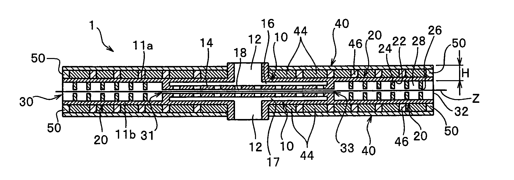
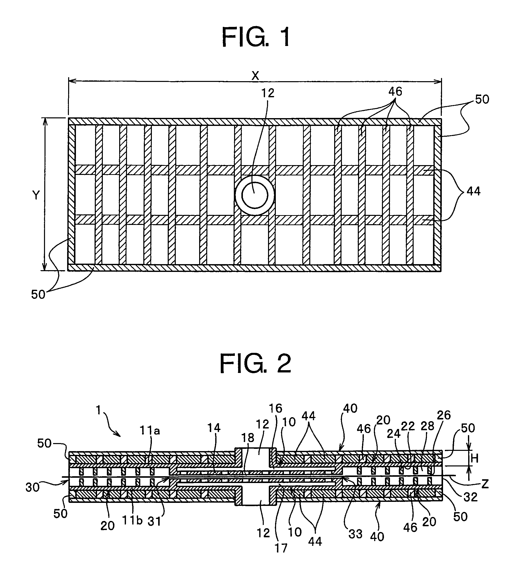
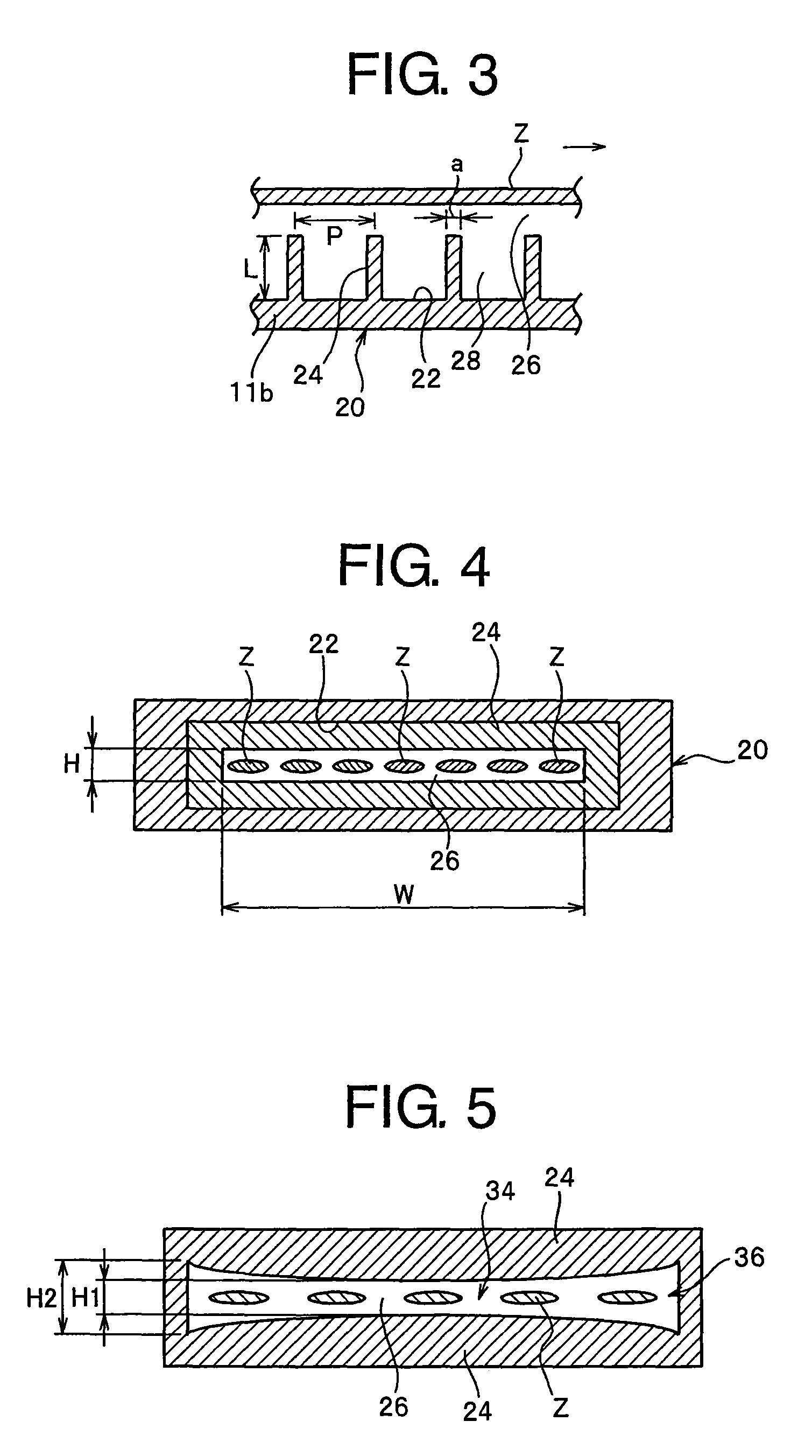
[0105]The treatment apparatus 1 illustrated in FIGS. 1 and 2 was designed to have the following dimensions: total length X of the apparatus 1: 4000 mm, total length of the pressure steam treatment chamber 10 in the direction of running fiber bundles Z: 1000 mm, total length of the labyrinth sealing chamber 20 in the direction of running fiber bundles Z: 1500 mm, width Y of the treatment apparatus: 1050 mm, height H of the rectangular-shaped opening section 26: 2 mm, and width W of the opening section 26: 1000 mm. In this case, the total length of the treatment apparatus 1 is the sum of each total length of the pressure steam treatment chamber 10 and two (first and second) labyrinth sealing chambers in the direction of running fiber bundles. Specifically, the total length of the labyrinth sealing chamber 20 is each length of the first and second seal sections 20 on one side thereof, and the first and second labyrinth sealing chambers 20 having this total length are arranged on each o...

examples 2 to 5

[0111]Numerical analysis was made using the same condition as that of Example 1 except that the thicknesses and number of the heat conductive members 44 and 46 and the ratio (A2 / A1) of the sectional area A2 of the heat conductive member to the area A1 enclosed by the plate member 50 with respect to an optional section parallel to the external wall member 40 were altered to those shown in FIG. 24A and FIG. 24B. The obtained results are shown in FIG. 24A and FIG. 24B.


PUM

PropertyMeasurementUnit
temperatureaaaaaaaaaa
lengthaaaaaaaaaa

Abstract

A pressure steam treatment apparatus according to the invention includes a pressure steam treatment chamber and labyrinth sealing chambers. The labyrinth sealing chambers are respectively arranged on a fiber bundle inlet and on a fiber bundle outlet of the steam treatment apparatus, having a running path of the fiber bundle in a horizontal direction and having plural labyrinth nozzles on top and bottom of the running path. The difference between a maximum value and a minimum value of the distance in the perpendicular direction of the top and bottom side labyrinth nozzles, of a pair of opposing labyrinth nozzles is 0.5 mm or smaller when the ambient temperature of the labyrinth sealing chamber is 140° C. This structure ensures that the energy cost can be reduced, the deformation of the apparatus and also, the raise of fuzz on the fiber bundle and fiber bundle breakage can be prevented at the same time.

Description

CROSS REFERENCE TO RELATED APPLICATIONS[0001]The present application is a 35 U.S.C. §371 national stage patent application of International patent application PCT / JP2012 / 050777, filed on Jan. 17, 2012, published as WO / 2012 / 108230 on Aug. 16, 2012, the text of which is incorporated by reference, and claims the benefit of the filing date of Japanese application nos. 2011-026960, filed on Feb. 10, 2011, and 2011-167343, filed on Jul. 29, 2011, the text of both of which is also incorporated by reference.TECHNICAL FIELD[0002]The invention relates to a pressure steam treatment apparatus preferably applied when fibers are drawn, specifically, to a pressure steam treatment apparatus in which fiber bundles are drawn under a pressure steam atmosphere, and particularly, to a pressure steam treatment apparatus capable of continuously treating a plurality of fiber bundles collectively in pressure steam treatment of a plurality of fiber bundles under a pressure steam atmosphere and to a method fo...

Claims


Application Information

Patent Timeline
Patent Type & Authority Patents(United States)
IPC IPC(8): D06B23/16D01F6/18D01F9/22D02G3/00D02J1/22D02J13/00D06B3/04D06B23/18D06M11/05D06M101/28
CPCD06B23/16D01F6/18D02J13/00D06M11/05D02G3/00D06B3/045D06B23/18D02J13/001D02J1/222D06B3/04D06M2101/28D01F9/22D02J1/22
Inventor MIZUTORI, YUKIHIROKAWAMURA, ATSUSHIINADA, HIROMASA
Owner MITSUBISHI CHEM CORP
Why Eureka
Try Eureka