MEMS microphone system for harsh environments

a microphone system and harsh environment technology, applied in the field of microphones, can solve the problems of limiting the operating temperature range of the microphone system, affecting the movement of the variable capacitor, and affecting the operation of the microphone, so as to prevent contaminants

Active Publication Date: 2014-09-23
INVENSENSE
View PDF40 Cites 12 Cited by
  • Summary
  • Abstract
  • Description
  • Claims
  • Application Information

AI Technical Summary

Benefits of technology

[0005]In some embodiments of the invention, the package base is a ceramic material providing a good thermal expansion match for the silicon microphone and any silicon processing elements attached to the package base. In preferred embodiments, the metal lids are connected with vias whose number and spacing reduces RFI that could affect microphone signals. The filter material may be a fabric with a controlled acoustic impedance and may be chosen from a polyetheretherketone fabric or a polytetrafluoroethylene fabric or an equivalent, in preferred embodiments of the invention. The microphone components may communicate with other system components external to the integrated circuit package by various means including side-brazed in-line leads, J-leads, gull-wing leads or by surface mounting the integrated circuit package on a circuit board, according to various embodiments of the invention.

Problems solved by technology

Undesirably, in addition to allowing access for acoustic signals, the aperture can allow access to contaminants that can compromise microphone operation.
For example, particles and moisture can enter the interior of the microphone and interfere with movement of the variable capacitor.
Additionally, thermal expansion mismatches between the microphone die and the package materials on which the microphone die is mounted can limit the operating temperature range for these microphone systems.
These problems often compromise condenser microphone systems operating in harsh environments having very high-temperatures, radio frequency interference / electromagnetic interference (“RFI” / “EMI”), and high volumes of airborne contaminants such as dirt, dust, and liquids.

Method used


Image

  • MEMS microphone system for harsh environments
  • MEMS microphone system for harsh environments
  • MEMS microphone system for harsh environments

Examples


Embodiment Construction

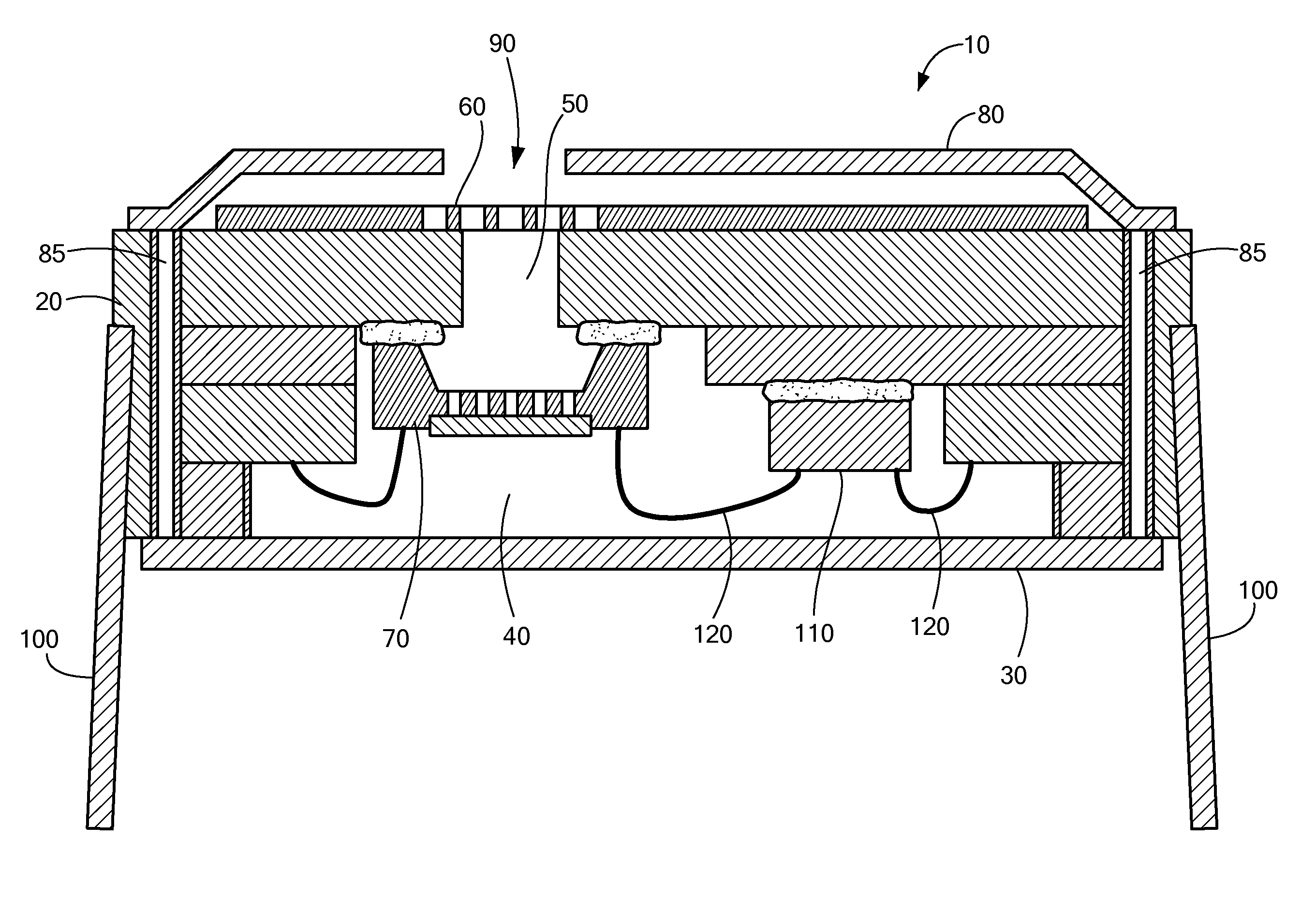
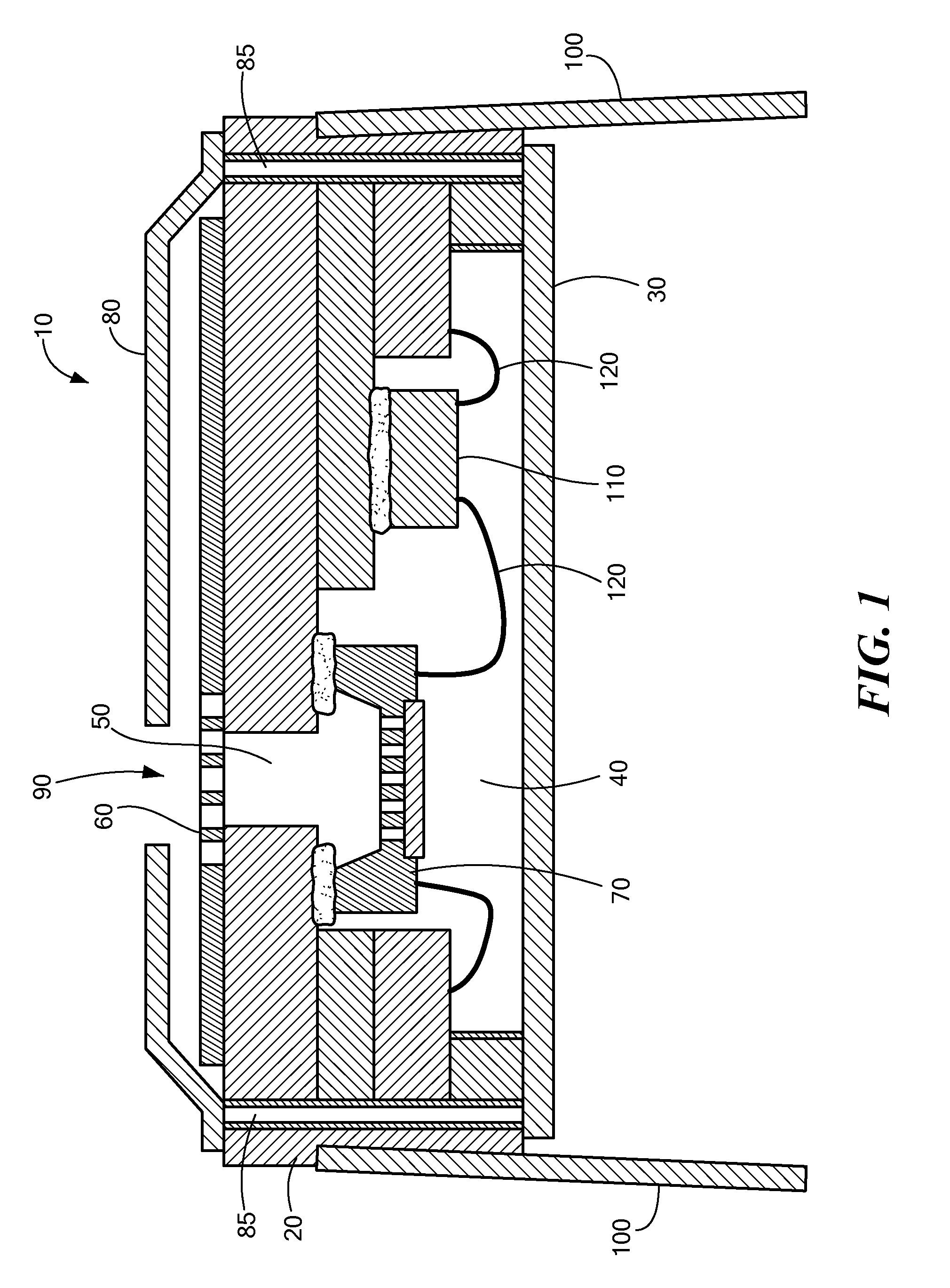
[0004]In a first embodiment of the invention there is provided a silicon MEMS microphone system in an integrated circuit package for use in harsh environments. The microphone system includes a package base which includes opposing first and second faces. The package base has a cavity in its first face and a first metal lid coupled to the first face of the package base covering the cavity to form an acoustic chamber. The package base includes an aperture through the second face of the package base for receiving audio signals into the acoustic chamber. A MEMS microphone is secured to the package base about the aperture within the acoustic chamber. A filter covers the aperture in the second face of the package base to prevent contaminants from reaching the microphone. A second metal lid encloses the second face of the base and the filter; includes an opening for allowing the audio signal to reach the acoustic chamber; and is electrically connected to the first metal lid, forming an EMI ...


PUM


Abstract

A MEMS microphone system suited for harsh environments. The system uses an integrated circuit package. A first, solid metal lid covers one face of a ceramic package base that includes a cavity, forming an acoustic chamber. The base includes an aperture through the opposing face of the base for receiving audio signals into the chamber. A MEMS microphone is attached within the chamber about the aperture. A filter covers the aperture opening in the opposing face of the base to prevent contaminants from entering the acoustic chamber. A second metal lid encloses the opposing face of the base and may attach the filter to this face of the base. The lids are electrically connected with vias forming a radio frequency interference shield. The ceramic base material is thermally matched to the silicon microphone material to allow operation over an extended temperature range.

Description

TECHNICAL FIELD[0001]The invention generally relates to microphones and, more particularly, the invention relates to packaged microphones for harsh environmentsBACKGROUND ART[0002]Microelectromechanical system (“MEMS”) condenser microphone dies typically have a diaphragm that forms a variable capacitor with an underlying backplate. Receipt of an audio signal causes the diaphragm to vibrate and generate a variable capacitance signal representing the audio signal. This variable capacitance signal can be amplified, recorded, or otherwise transmitted to another electronic device. Such microphones typically are enclosed in a package to shield sensitive microphone components from environmental conditions.[0003]These microphone packages have an aperture that allows acoustic signals to reach the microphone. Undesirably, in addition to allowing access for acoustic signals, the aperture can allow access to contaminants that can compromise microphone operation. For example, particles and moist...

Claims


Application Information

Patent Timeline
Patent Type & Authority Patents(United States)
IPC IPC(8): H01L29/84
CPCH04R19/04H04R1/086H04R19/005H04R31/00H01L2224/48091H01L2224/48137H01L2224/48227H01L2224/73265H01L2924/00014
Inventor HARNEY, KIERAN P.GAO, JIAKHENKIN, ALEKSEY S.
Owner INVENSENSE
Why Eureka
Try Eureka