Omnidirectional buoyant cable antenna for high frequency communications

a high-frequency communication and buoyant cable technology, applied in special-purpose vessels, subaqueous/subterranean adaption, transportation and packaging, etc., can solve the problems of limited utility of unidirectional signal coverage and limited radio frequency communication for submerged underwater vehicles, so as to reduce seawater losses, increase radiated power, and eliminate signal null areas

Inactive Publication Date: 2014-09-23
UNITED STATE OF AMERICA THE
View PDF5 Cites 5 Cited by
  • Summary
  • Abstract
  • Description
  • Claims
  • Application Information

AI Technical Summary

Benefits of technology

[0011]These objects are accomplished through the use of a buoyant cable antenna with a vertical antenna component that eliminates signal null areas. The antenna of the present invention comprises a floating cable having four identical antenna elements that are arranged in a cross configuration. The antenna elements are attached to and protrude from the floating cable. While floating on the water surface, the antenna may rotate freely with minimal signal loss with one antenna element always extended abov...

Problems solved by technology

Radio frequency communication for submerged underwater vehicles is currently limited to unid...

Method used


Image

  • Omnidirectional buoyant cable antenna for high frequency communications
  • Omnidirectional buoyant cable antenna for high frequency communications

Examples


Embodiment Construction

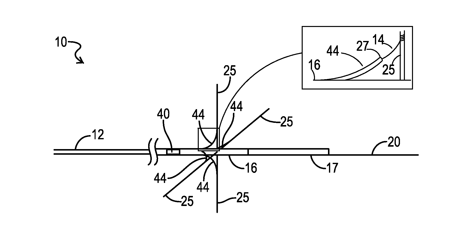
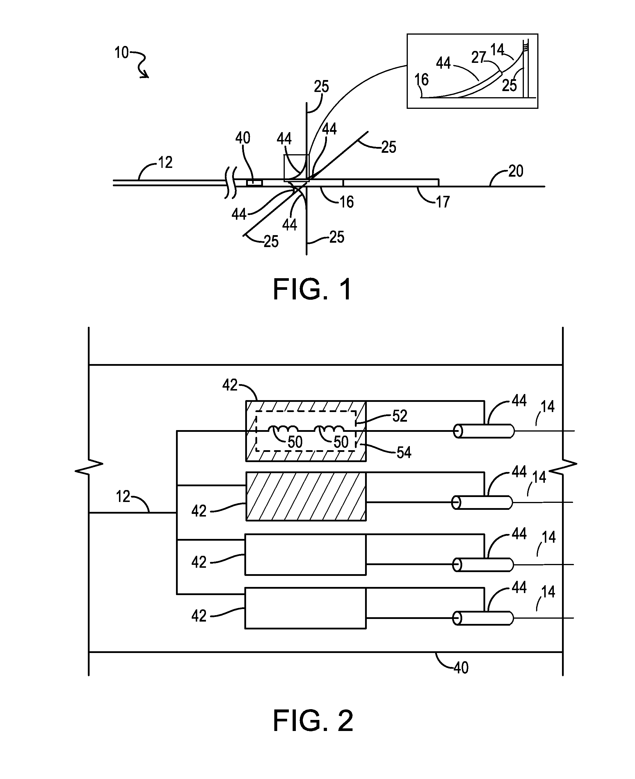
[0015]Referring to FIG. 1, the present invention teaches a buoyant cable antenna 10 that is towed by a submerged underwater vehicle (not shown) as the antenna 10 floats on the surface of the water 20. The antenna 10 is electrically connected to the underwater vehicle via a coaxial cable transmission line 12. The antenna 10 is composed of three sections; 1) an encapsulating cylindrical encasement 16; 2) a buoyant section 17 comprising a cable made of polyethylene foam that provides the buoyancy in seawater; and 3) four identical antenna elements 14 that are attached to and protrude from encasement 16.

[0016]In a preferred embodiment, encasement 16 is made from a potting compound such as a thermo-setting plastic or a silicone rubber gel that is water tight, flexible, tear resistant and meets the tensile requirements for towing a buoyant cable antenna at specified speeds as well as deployment and retrieval by the BRA-24 system. In a preferred embodiment encasement 16 encapsulates the el...


PUM


Abstract

The invention is a buoyant cable antenna that is towed on the surface of a body of water by a submerged underwater vehicle to allow communication coverage in an omnidirectional pattern in the VHF frequency range and that is also compatible with existing buoyant cable antenna deployment and retrieval systems. The antenna of the present invention comprises a floating cable having four identical antenna elements that are arranged in a cross configuration. The antenna is designed with a system of four shielded inductor units connected in series with the antenna elements to reduce the losses to seawater by the submerged elements and to tune the exposed vertical element and its feed-cable capacitance to resonance which results in greatly increased radiated power at the design frequency of approximately 10-30 MHz.

Description

STATEMENT OF GOVERNMENT INTEREST[0001]The invention described herein may be manufactured and used by or for the Government of the United States of America for governmental purposes without the payment of any royalties thereon or therefore.CROSS REFERENCE TO OTHER RELATED APPLICATIONS[0002]Not applicable.BACKGROUND OF THE INVENTION[0003](1) Field of the Invention[0004]The present invention relates to antennas for use with an underwater vehicle, and more specifically to a buoyant cable antenna that is towed by a submerged underwater vehicle to allow communication coverage in an omnidirectional pattern in the frequency range of 10 MHz to 30 MHz that is preferably compatible with existing buoyant cable antenna deployment and retrieval systems.[0005](2) Description of the Prior Art[0006]Radio frequency communication for submerged underwater vehicles is currently limited to unidirectional signal coverage. Buoyant cable antenna systems consisting of a single floating horizontal antenna ele...

Claims


Application Information

Patent Timeline
IPC IPC(8): H01Q1/34
CPCH01Q1/04H01Q1/34B63G8/38
Inventor MILESKI, PAUL, M.
Owner UNITED STATE OF AMERICA THE
Why Eureka
Try Eureka