Remote monitoring and control system comprising mesh and time synchronization technology

a technology of remote monitoring and control system, applied in the direction of wireless architecture, electric generator control, instruments, etc., can solve the problems of utility field services department perpetual challenges with these processes, consuming a great amount of resources, and three processes consuming an average work effort of 90%

Active Publication Date: 2014-09-23
SABERI ALI
View PDF8 Cites 94 Cited by
  • Summary
  • Abstract
  • Description
  • Claims
  • Application Information

AI Technical Summary

Benefits of technology

[0008]In one embodiment of the invention, the system described herein may be used to remotely control multiple utility grids and commodity distribution systems including but not limited to electricity, water and gas grids and distribution systems; industrial application and infrastructure including but not limited to manufacturing and pharmaceutical plants. In another embodiment of the invention, the system uses a synchronized wireless network with Radiant Configuration Protocol (RCP) and a single application system. In a further embodiment of the invention, the Radiant Configuration Protocol (RCP) comprises a light weighted network configuration that utilizes optimization of power usage and minimizing of power budgeting.

Problems solved by technology

Utilities that distribute commodities, such as gas, water, or electricity over a commodity distribution network face a perpetual challenge with meter reading, disconnection from, and reconnection to the grid.
These three processes consume an average work effort of 90% for a utility's field services department, especially when it comes to residential and commercial accounts which contribute to a lower revenue base and higher maintenance cost.
However, utilities face perpetual challenges with these processes.
First, a utility company may deploy field agents to manually perform these processes where these utility meters are located, consuming a great amount of resources.
Second, not only is this highly inefficient, some field agents, without proper supervision, may be prone to corrupt practices (e.g., taking bribes for recording inaccurate readings).
Third, because utility meters are located in remote locations, they are highly susceptible to tampering and pilfering.
This may lead to inaccurate readings, uncompensated utility services, lack of notice of problems to the utility company, other losses and setbacks.
Further, it is often difficult for the service person to access the meter for reading, inspection, and maintenance.
Therefore, manual meter reading is a highly labor intensive, inefficient, and expensive endeavor.
These estimated billings often lead to customer complaints.
Although reducing efforts on the meter reading end, the billing process is made complex, and this complexity may not reduce the possibility of inaccurate billing until the reassessment corrections occur.
These and other drawbacks exist with current systems.

Method used


Image

  • Remote monitoring and control system comprising mesh and time synchronization technology
  • Remote monitoring and control system comprising mesh and time synchronization technology
  • Remote monitoring and control system comprising mesh and time synchronization technology

Examples


example 1

Advanced Metering Infrastructure (AMI)

[0347]The invention described herein provides a system and method to remotely read meters, remotely control the connection status, may allow for encrypted data communication, and real time alarms. The system and method described herein may be integrated into any existing infrastructure or network to upgrade a preexisting system to an AMI system (e.g., retrofit).

[0348]In another embodiment of the invention, the systems described herein may provide utility support (e.g., consulting and planning, asset management, engineering services, inspection and treatment services, storm / disaster assistance) for operations in outage management and grid component failure (e.g., transformer explosion). In another embodiment, the system may comprise telemetry to provide an utility organization with the required information to monitor and prevent outages and grid component failures.

[0349]In an alternate embodiment of the invention, the system and method described ...

example 2

Energy Harvesting Device Requirements

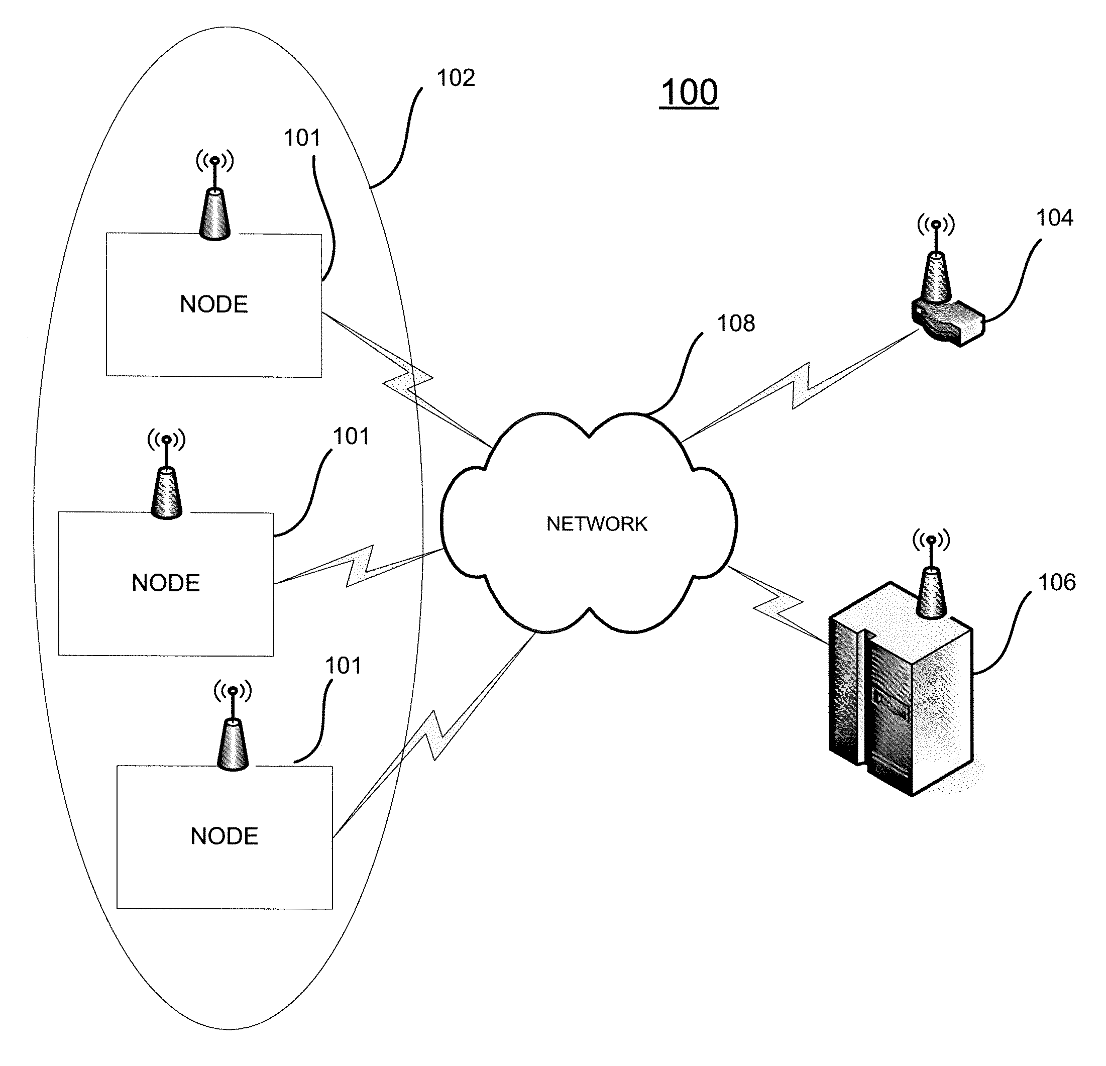
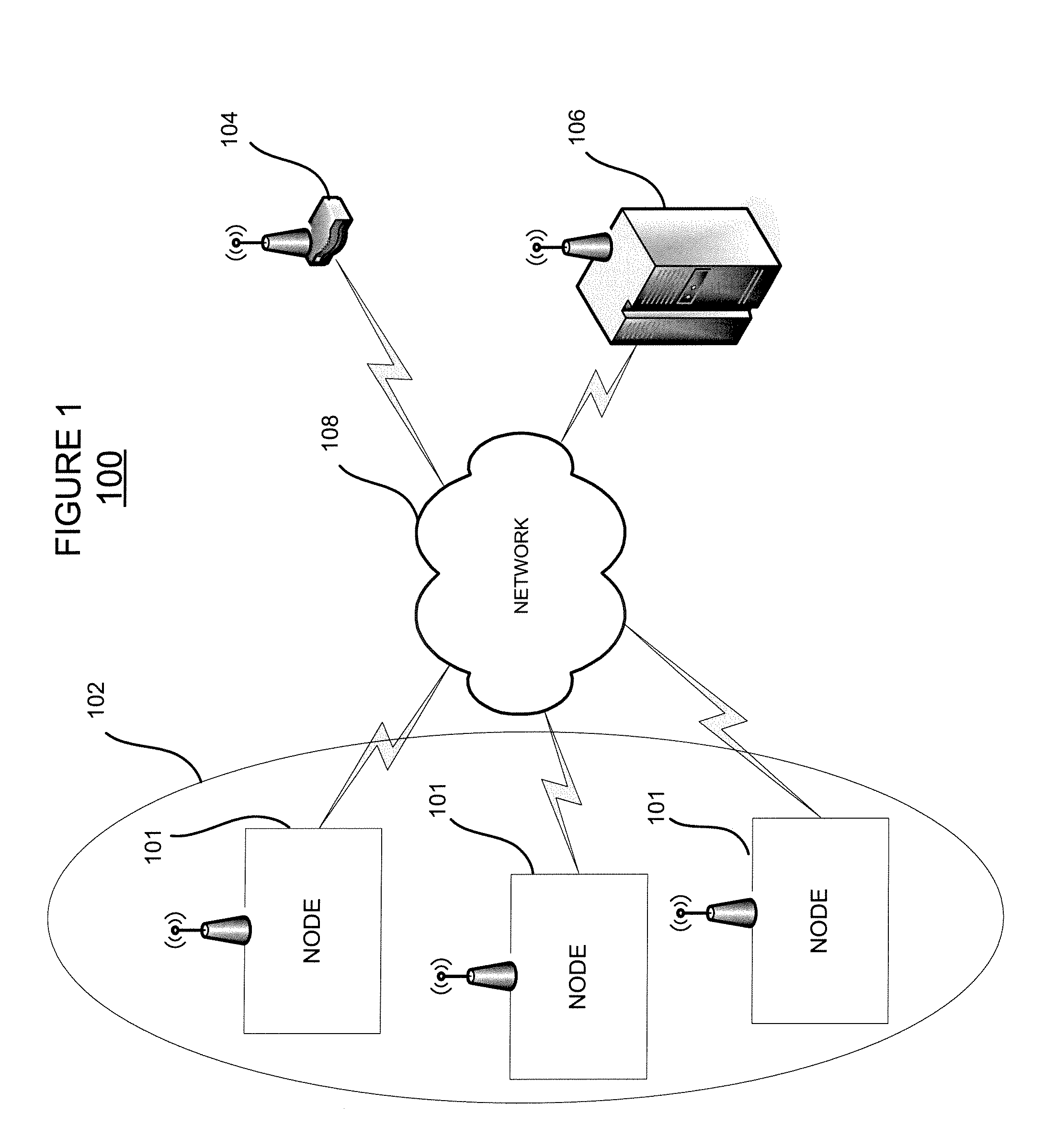
[0351]The system described herein require little power over a day to operate. For example, most of the time the nodes described herein are in a “sleep mode” that may use less than 12 mAmp (micro Amperes) of current. The active time may be less than 2 minutes per day for a routing node 101 and 4 minutes per day for a meter node 101. The energy harvesting device may only require magnetic coupling through a high strength plastic wall.

[0352]The total battery drain, which may include the self-discharge of the battery may vary from about 7 coulombs-per-day to 10 coulombs-per-day depending on the node's position in the network 108 and status. One type of batteries suitable for use in the invention are NiMH batteries which are long storage life batteries with about 2000 mAHr capacity allowing for about 7200 coulombs of charge available. NiMH batteries may last at least a year and a half with no charging from the energy harvesting device in water valve sh...

example 3

Advanced Industrial Coordination Infrastructure

[0356]The system described herein may allow for remote monitoring and control of an industrial infrastructure (e.g., factory, assembly lines, chemical synthesis plants, food processing plants, mills). A control unit 106 may control the timing, duration, function, temperature, action, and frequency of the equipment; synchronize or stagger the factory output; and preferentially deactivate and active in a pattern (e.g., change the factory output to accommodate may change in orders).

[0357]The system and method described herein may allow, on an ongoing basis, the history of key metrics (e.g., distribution loading, network status) from which key operational metrics of transformer performance may be collected and analyzed. Predictive maintenance and the replacement and upgrade of network infrastructure (e.g., machines, transformers, parking meters, traffic lights, meters, devices) may be managed more effectively and efficiently. The distributi...


PUM


Abstract

A remote monitoring and control system comprising synchronized wireless MESH technology for remote monitoring and control of utility grids (e.g., utility meters), commodity distribution networks, industrial equipment, and infrastructure including remote disconnection / connection and self-generating power.

Description

CROSS-REFERENCE TO RELATED APPLICATIONS[0001]This application is the U.S. National Stage application of international patent application claims the benefit of U.S. Provisional Patent Application No. 61 / 054,779, filed May 20, 2008 and U.S. Provisional Patent Application No. 61 / 108,312, filed Oct. 24, 2008, the disclosures of both of which are herein incorporated by reference in their entirety.FIELD OF THE INVENTION[0002]The present invention relates to a system and method for remote monitoring and control, and more specifically, to remote utility meter reading and control of water, electricity, and gas meters using synchronized wireless communications technology, remote connection and disconnection, and an energy-harvesting device.BACKGROUND OF THE INVENTION[0003]Utilities that distribute commodities, such as gas, water, or electricity over a commodity distribution network face a perpetual challenge with meter reading, disconnection from, and reconnection to the grid. These three pro...

Claims


Application Information

Patent Timeline
Patent Type & Authority Patents(United States)
IPC IPC(8): G05D3/12F16K31/02H02P9/04F03B13/10G05D17/00G08C19/22G08C19/20G08C15/06H04Q9/00G05D11/00G05D9/00G05D5/00F16K31/08
CPCF16K37/0091F16K31/046H04Q9/00H04Q2209/43H04Q2209/60H04Q2209/886
Inventor SABERI, ALIGILBERT, JAMES ROBERTLAY, KEVIN
Owner SABERI ALI
Why Eureka
Try Eureka