Buffering device for the operating mechanism of a switchgear, and method of lubrication thereof

a technology of operating mechanism and buffer device, which is applied in the direction of damper-spring combination, liquid-based damper, packaging, etc., can solve the problems of increasing the pressure of operating fluid, reducing the flow rate of operating fluid out of the internal cylinder, and reducing the braking force, so as to reduce the size and weight of the device, reduce the cost of packing, and reduce the effect of braking for

Active Publication Date: 2014-09-30
KK TOSHIBA
View PDF14 Cites 6 Cited by
  • Summary
  • Abstract
  • Description
  • Claims
  • Application Information

AI Technical Summary

Benefits of technology

[0030]With the buffering device of this embodiment of the present invention, the operating fluid can be utilized in a high-pressure condition at the piston portion, so a large braking force can be generated with a small-diameter piston and cylinder, so reduction in size and weight of the device can be promoted. Also, since the high pressure is not directly applied to the sliding sealing portion, expensive packing can be eliminated, contributing to lower costs and improving reliability with regard to leakage of operating fluid.
[0031]Furthermore, the construction is one in which change in volume of the operating fluid can be absorbed by combination of the second piston with the second return spring: in this way, there is no need for an air layer on the operating fluid, so stable braking force can be obtained by reliably preventing admixture of the air with the operating fluid. Furthermore, the braking force of the buffering device does not act during the closure operation of the switchgear, so there is no loss of drive energy of the operating mechanism, so improving the efficiency of utilization of the drive energy. Also, with the method of lubrication of the buffering device of this embodiment of the present invention, no air is mixed with the operating fluid, so the lubrication task can be performed rapidly.

Problems solved by technology

Consequently, the rate of flow of operating fluid out from the internal cylinder decreases, with the result that the pressure of the operating fluid rises, generating braking force.

Method used


Image

  • Buffering device for the operating mechanism of a switchgear, and method of lubrication thereof
  • Buffering device for the operating mechanism of a switchgear, and method of lubrication thereof
  • Buffering device for the operating mechanism of a switchgear, and method of lubrication thereof

Examples


first embodiment

[1] First Embodiment

Construction

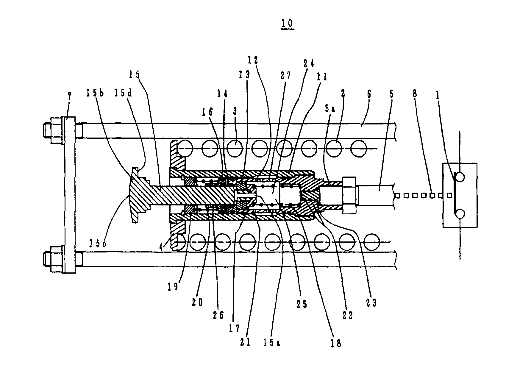
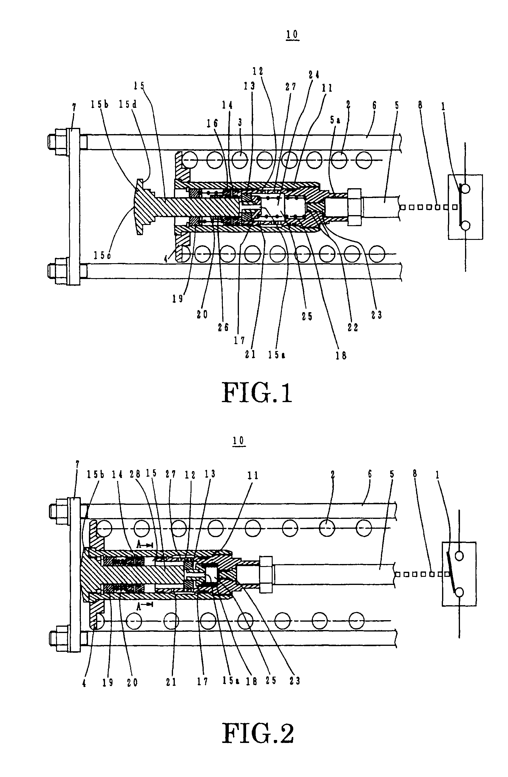
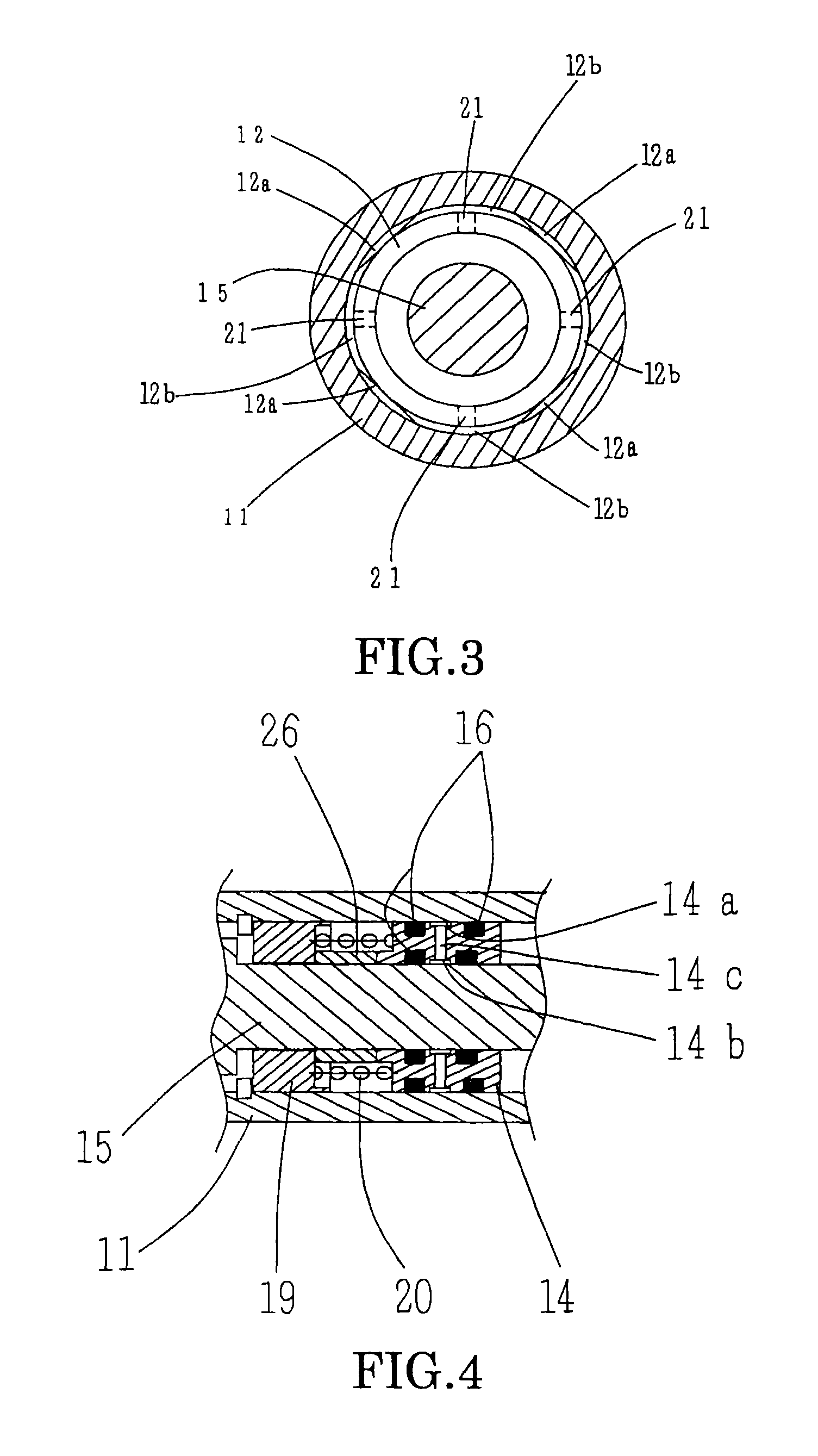
[0042]First of all, a first embodiment of a buffering device for the operating mechanism of the switchgear according to the present invention will be described with reference to FIG. 1 to FIG. 4. FIG. 1 is a cross-sectional view showing the closure condition of a buffering device 10 for the operating mechanism of a switchgear; FIG. 2 is a cross-sectional view showing the interruption condition of the buffering device 10 shown in FIG. 1. FIG. 3 is a view of the buffering device of FIG. 2 in the direction of the arrows A-A. FIG. 4 is a detail view to a larger scale showing a portion of the buffering device of FIG. 2.

[0043]The buffering device 10 serves to reduce the speed of the movable contact 1 constituting the moving body in the operating mechanism of the switchgear. Operating fluid 24 is sealed in the interior of the buffering device 10: braking force is generated by compression of the operating fluid 24 immediately before arrival at the terminal po...

second embodiment

[2] Second Embodiment

Construction

[0080]Next, a second embodiment of a buffering device for the operating mechanism of a switchgear according to the present invention will be described with reference to FIG. 5. FIG. 5 is a cross-sectional view showing the closed condition of the second embodiment of a buffering device for the operating mechanism of a switchgear. It should be noted that parts that are identical with or similar to corresponding parts in the first embodiment are given the same reference numerals, to avoid duplication of description.

[0081]In the second embodiment, the mounting position of the buffering device 10 shown in FIG. 1 and the construction of the plug 23 and second return spring seat 19 are altered. Specifically, a construction is adopted in which the external cylinder 11 is fixed to the restraining plates 7, the spring rod 5 is fixed to the interruption spring seat 4, and the end of the spring rod 5 and the end of the piston rod 15 are engaged in such a way tha...

third embodiment

[3] Third Embodiment

Construction

[0091]Next, a third embodiment of the buffering device for the operating mechanism of a switchgear according to the present invention will be described with reference to FIG. 6 and FIG. 7. FIG. 6 is a cross-sectional view showing the closure condition of the third embodiment and FIG. 7 is a view showing the interruption condition of the device of FIG. 6. It should be noted that parts that are identical with or similar to corresponding parts in the first embodiment and a second embodiment are given the same reference numerals, to avoid duplication of description.

[0092]The third embodiment is an improvement on the second embodiment and is characterized in that the construction is modified by dispensing with the first return spring 18 of the buffering device 10 shown in FIG. 5. Specifically, a stud 32 extending on the opposite side to that of the movable contact 1 is provided on the restraining plate 7 and a cylinder fixing plate 31 is mounted on the stu...


PUM

PropertyMeasurementUnit
pressureaaaaaaaaaa
speedaaaaaaaaaa
pressureaaaaaaaaaa

Abstract

A piston rod (15) and a first piston (13) are arranged in the interior of an external cylinder (11) and internal cylinder (12); a second piston for absorbing the change of volume of operating fluid (24) is also arranged therein. Also, a first return spring (18) for returning the piston rod (15) to the interruption position is provided and a second return spring (20) for returning the operating fluid 24 into the high-pressure chamber (25) by pressurizing the second piston (14) is provided. In addition, the air in the interior of the buffering device (10) is withdrawn by a vacuum pump (38), and operating fluid (24) is thus introduced in a degassed condition.

Description

CROSS-REFERENCE TO RELATED APPLICATION[0001]This application claims benefit of priority from Japanese application number JP 2009-234881 filed Oct. 9, 2009, the entire contents of which are incorporated by reference herein.TECHNICAL FIELD[0002]The present invention relates to an operating mechanism for a switchgear in which opening / closing operation of the switchgear is performed by operating a moving body including an electrical contact, and, in particular, it relates to a buffering device for braking the moving body when operation is performed, and to a method of lubrication thereof.BACKGROUND ART[0003]In general, the operating mechanism for a high-voltage switchgear is operated by opening / closing operation (interruption / closure operation) of the switchgear, by reciprocating drive of an electrical contact of the switchgear between the open and closed positions. In order for the switchgear to exhibit good interruption performance, it is important for the moving body including the el...

Claims


Application Information

Patent Timeline
Patent Type & Authority Patents(United States)
IPC IPC(8): F16F9/00H01H3/60H01H33/30
CPCH01H33/304H01H3/605H02B13/0354F16F13/007F16N13/00F16F9/432F16F2230/06F16F9/18F16F9/32F16F9/48H01H33/42
Inventor OHDA, YOSHIAKIKOBAYASHI, YOSHIKATASHIMIZU, MASAHARUMARUSHIMA, SATOSHITAKAGI, HIROKAZUINOUE, TOORU
Owner KK TOSHIBA
Why Eureka
Try Eureka