Imaging apparatus that switches between hardware image processor and software image processor

a technology of hardware image processor and software image processor, which is applied in the field of imaging equipment, can solve the problems of increasing the number and noticeable degradation of the image, and achieve the effect of high sensitivity of the imaging device and high precision moving imag

Active Publication Date: 2014-09-30
RICOH IMAGING COMPANY
View PDF5 Cites 5 Cited by
  • Summary
  • Abstract
  • Description
  • Claims
  • Application Information

AI Technical Summary

Benefits of technology

[0007]According to the present invention, it is possible to provide an imaging apparatus that is capable of obtaining a high-precision moving image even when the sensitivity of the imaging device is high.

Problems solved by technology

However, when an increase in the sensitivity of the imaging device is accompanied by an increase in the number of defective pixels as correction targets, noticeable degradation of the image occurs due to the transfer, that is, the replacement of defective pixels.

Method used


Image

  • Imaging apparatus that switches between hardware image processor and software image processor
  • Imaging apparatus that switches between hardware image processor and software image processor
  • Imaging apparatus that switches between hardware image processor and software image processor

Examples


first embodiment

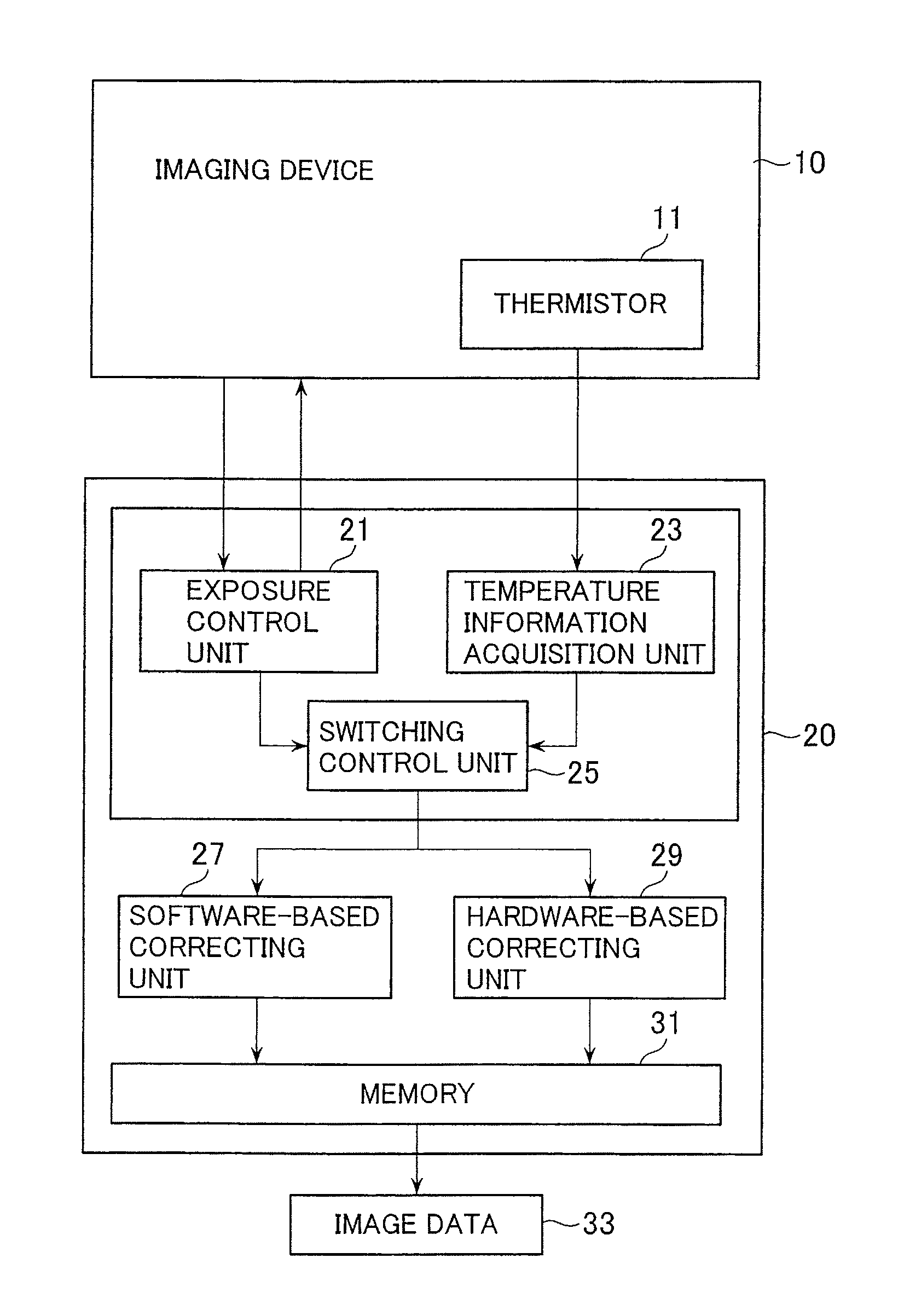
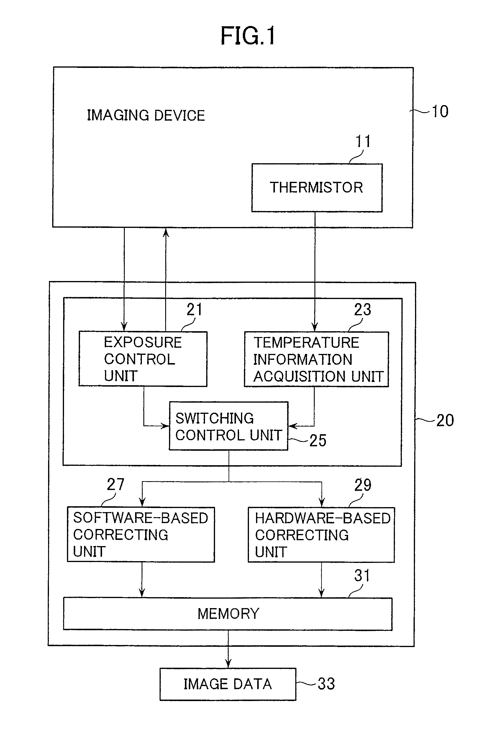
[0013]Hereinafter, the invention will be described by referring to the drawings. FIG. 1 is an electrical schematic diagram of a digital camera according to the present invention. An image signal, which is generated by an imaging device 10, is processed in an electronic control unit 20 and image data 33 is output to a monitor (not illustrated).

[0014]The imaging device 10 is equipped with a thermistor 11 which detects the temperature of the imaging device 10. The exposure control unit 21 is electrically connected to the imaging device 10 and performs various controls including the setting of the sensitivity of the imaging device 10. A temperature information acquisition unit 23 is connected to the thermistor 11 and detects the temperature of the imaging device 10. As described below, a switching control unit 25 selectively operates one of either a software-based correcting unit 27 or a hardware-based correcting unit 29 depending on information from the exposure control unit 21 and the...

third embodiment

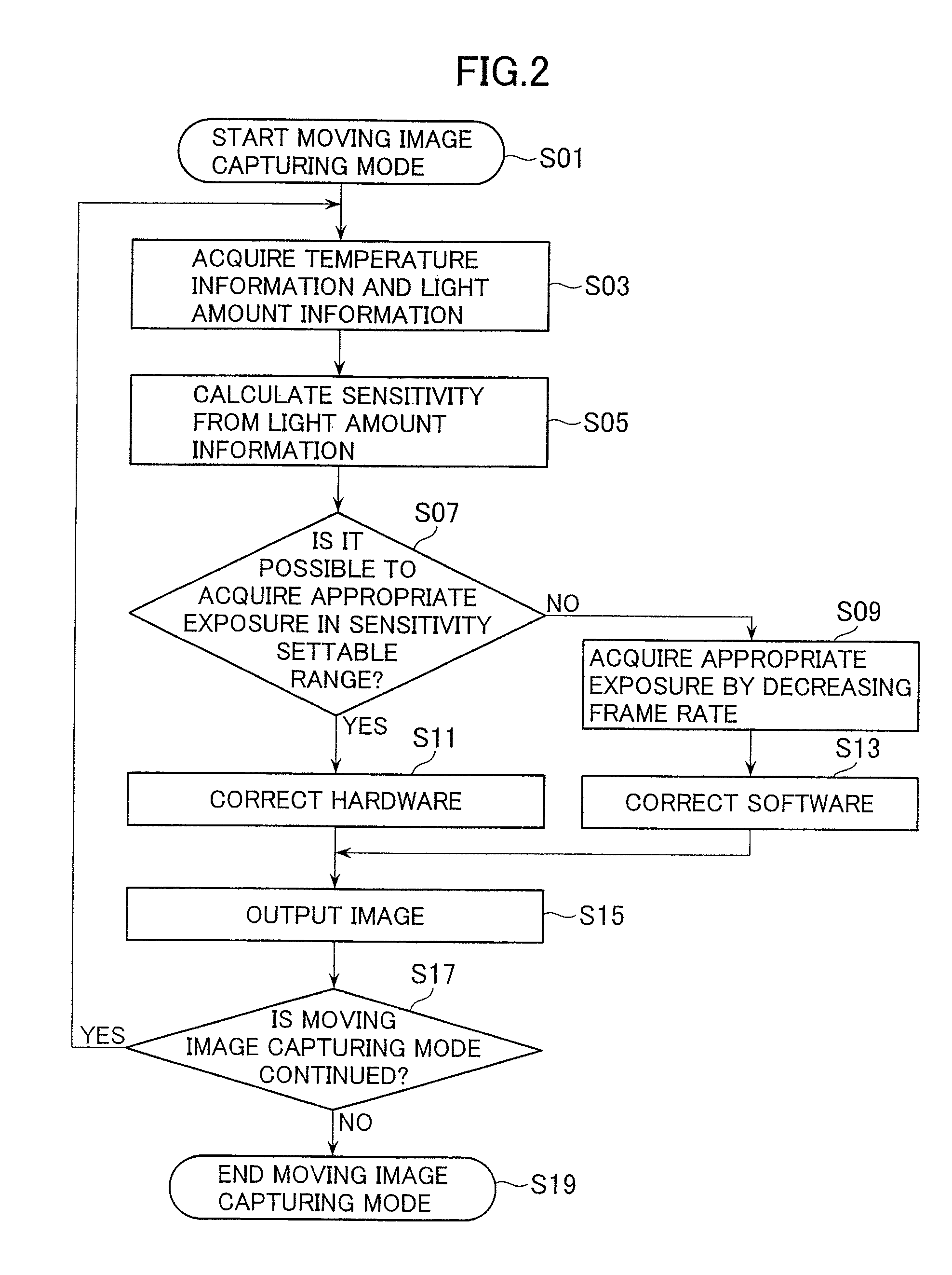
[0025]In the third embodiment, either hardware or software is used to process the image signal while the frame rate of the normal imaging mode is maintained. That is, the embodiment may be applied to a case where a processor (not illustrated) having a high image-processing capability is provided.

[0026]The switching reference value is defined as the product of the constant (A) and the set sensitivity value plus the product of the constant (B) and the temperature of the imaging device 10. In step S06, when it is determined that the switching reference value is larger than the constant C, step S13 is performed. On the other hand, when the switching reference value is smaller than the constant C, step S11 is performed.

[0027]There is a tendency for the number of defective pixels to increase as the temperature and sensitivity of the imaging device 10 both increase. That is, in step S06, when the switching reference value is determined to be larger than the constant C, there will be a larg...


PUM


Abstract

An imaging apparatus capable of capturing a moving image with an imaging device is equipped with a first image-processing device that uses hardware to process images captured by the imaging device and a second image-processing device that processes captured images with software. The imaging apparatus includes an image-processing switching device that selectively operates one of either the first image-processing device or the second image-processing device. The imaging apparatus includes a light-detection device that detects the amount of light received by the imaging device and a sensitivity adjustment device that increases the sensitivity of the imaging device as the amount of light decreases. The image-processing switching device operates the first image-processing device when the sensitivity is lower than a predetermined value and operates the second image-processing device when the sensitivity is higher than the predetermined value.

Description

BACKGROUND OF THE INVENTION[0001]1. Field of the Invention[0002]The present invention relates to an imaging apparatus that performs a correction process on a moving image.[0003]2. Description of the Related Art[0004]Hitherto, for imaging apparatuses that capture moving images a technique has been developed so that an image signal can be processed while a predetermined frame rate is maintained. There is a known method that uses software to process a moving image signal after it has been processed using hardware. Accordingly, the number of times a memory expansion process is carried out may be suppressed to a minimum to reduce the entire processing time so that the image signal can be processed without decreasing the frame rate, as described in US Unexamined Patent Publication No. US2007-230779A.SUMMARY OF THE INVENTION[0005]In the image-processing technique that uses hardware, a defective pixel is corrected by replacement with another pixel. However, when an increase in the sensitivi...

Claims


Application Information

Patent Timeline
Patent Type & Authority Patents(United States)
IPC IPC(8): H04N5/235H04N5/228H04N5/232H04N5/367
CPCH04N5/23245H04N5/2351H04N5/367H04N23/667H04N23/71H04N25/68
Inventor ASAKURA, NAOTO
Owner RICOH IMAGING COMPANY
Why Eureka
Try Eureka