Jet type gas cooker

a gas cooker and jet technology, applied in the field of jet type gas cookers, can solve the problems of excess hazard gas emission, fuel gas cannot be fully burned, waste of energy, etc., and achieve the effect of enhancing heat exchange rate and reducing hazard gas emission

Inactive Publication Date: 2014-10-14
HE MEISHUN
View PDF13 Cites 0 Cited by
  • Summary
  • Abstract
  • Description
  • Claims
  • Application Information

AI Technical Summary

Benefits of technology

[0007]The invention is advantageous in that it provides a jet type gas cooker, which is able to well premix the fuel gas with the air, reduce the emission amount of hazard gas, and to enhance the heat exchanging rate between the flame of the fuel gas and the cooking wares.
[0016]Therefore, the jet type gas cooker of the present invention at least has the following advantages. The gas flow disturbing mixer disposed within the mixing chamber of the burner head to enforcedly well premix the air and the fuel gas in a turbulent manner. Therefore, the well mixed air and fuel gas provides adequate oxygen for fully burning the combustion gas, so as to save the energy of the fuel of the fuel gas and to minimize the emission of hazard gases. The air blow housing is provided at the bottom of the hollow mixing pipe of the burner head for guiding the air flow into the mixing chamber of the burner head, so that the supply of oxygen is increased, so as to enhance the mixing effect between the air and the fuel gas. Meanwhile, the air flow from the air blow housing will substantially increase the pressure of the mixed fuel gas with air within the mixing chamber of the burner head to ensure the mixed fuel gas with air being upwardly ejected at the flame controller. Therefore the distance between the flame of the burning fuel gas at the flame controller and the bottom of the cooking utensil or appliance is substantially minimized to enhance the heat transferring efficiency from the flame to the cooking utensils. The supply of oxygen for burning fuel gas is also increased for relatively more fully burning the combustion gas as the mixed fuel gas with air. The partition element is disposed within the mixing chamber of the burner head. Therefore, the fuel gas is firstly mixing with the air in the first mixing room, and then secondly mixing with the air in the second mixing room via the gas flow disturbing mixer to further enforce the mixing effect between the air and the fuel gas, so that the fuel gas is able to be highly mixed with the air, so as to fully burn the fuel gas to maximize the utilizing energy of the combustion gas.

Problems solved by technology

However, this type of gas stove has two main concerns.
First, the fuel gas burning on the burner head is only relied on the oxygen in the ambient air for combusting the gas without premixing with oxygen before starting burning, so that the fuel gas is unable to be fully burned.
Thereby, the incompletely burned fuel gas causes the waste of energy and the excess amount of hazard gas emission thereof.
Secondly, heat transferring efficiency of the gas stove depends on the distance between the burning flame and the bottom heating portion of the cooking pan, so that the heat exchanging rate therebetween is low.
Therefore, the fuel gas is still unable to well mix with the air to fully burn the combustion gas.
On the other hand, no matter the bottled fuel gas or the pipeline conveyed combustion gas, the pressure of the gas nozzle to jet the fuel gas therefrom is low.
Therefore, the performance of the flame of the combustion gas, which usually applies the jet pressure of the gas nozzle for burning on the flame control lid, can not be optimized or significantly enhanced.

Method used


Image

  • Jet type gas cooker
  • Jet type gas cooker
  • Jet type gas cooker

Examples


Embodiment Construction

[0033]The following will disclose the detailed description with the preferred embodiments and the accompanying drawings.

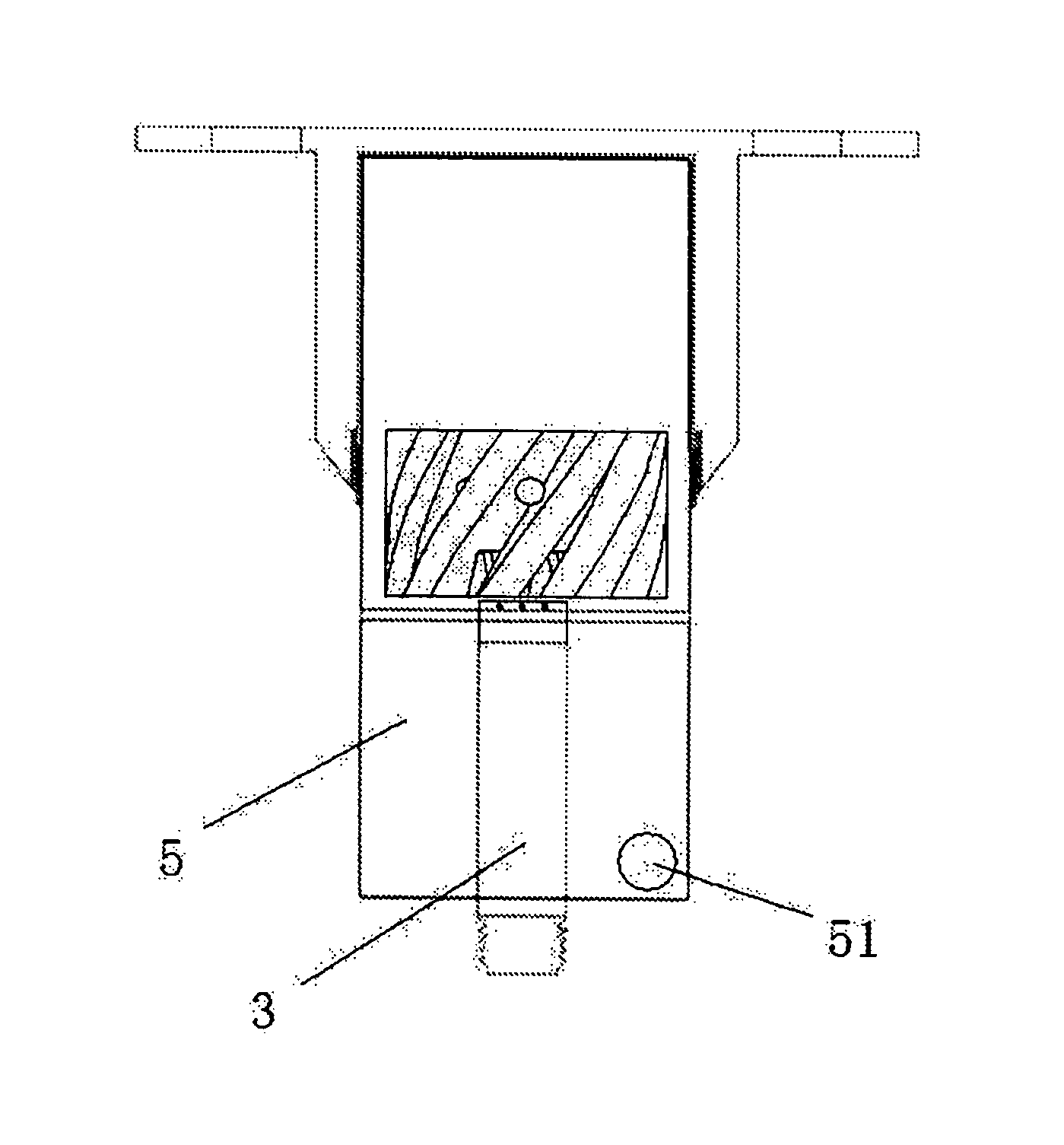
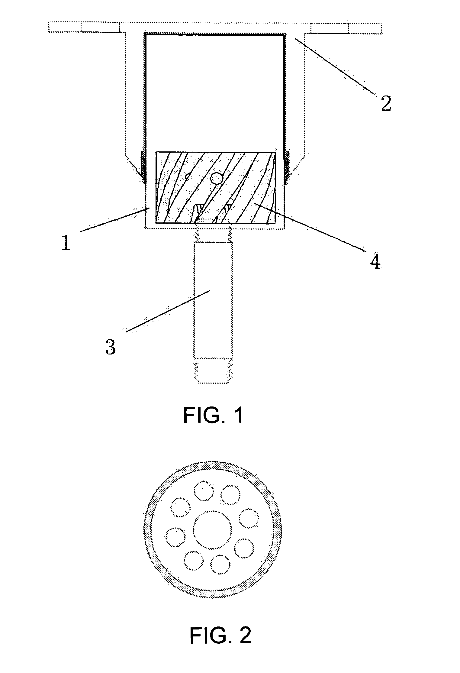
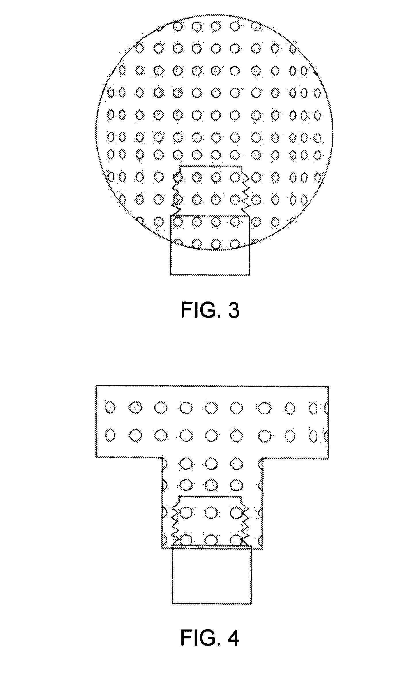
[0034]Referring to FIG. 1 of the drawings, a jet type gas cooker according to a preferred embodiment of the present invention is illustrated, wherein the jet type gas cooker comprises a burner head 1 having a mixing chamber for premixing fuel gas with air being the fuel gas is initially ignited. The gas cooker further comprises a grid element 11 disposed at the bottom side of the mixing chamber of the burner head 1, wherein the grid element 11 has a plurality of mesh holes, as shown in FIG. 2, for guiding the air entering into the mixing chamber of the burner head 1. The gas cooker further comprises a flame controller 2 as a cover seated on top of the burner head 1, wherein the flame controller 2 has a plurality of communication holes for communicating with the mixing chamber of the burner head 1. It is appreciated that the flame controller 2 can be integrally form...


PUM


Abstract

A jet type gas cooker includes a burner head having a mixing chamber therewithin, wherein a grid element is disposed at a bottom side of the mixing chamber of the burner head; a flame controller seated on top of the burner head; a fuel gas pipe extended to the bottom side of the burner head for ejecting fuel gas into the mixing chamber; and a gas flow disturbing mixer supported within the mixing chamber of the burner head for mixing the fuel gas with air to form a combustion gas within the mixing chamber.

Description

BACKGROUND OF THE PRESENT INVENTION[0001]1. Field of Invention[0002]The present invention relates to a jet type gas cooker, and more particularly to a burner of the jet type gas cooker.[0003]2. Description of Related Arts[0004]Gas stove or gas cooking range is common household appliance or equipment commonly seen in most of the modern family. There is variety of types of fuel gas stoves, such as the gas stoves using liquid petroleum fuel, coal, natural gas, or biogas as the combustible gases for generating the heat energy.[0005]The traditional gas stoves basically comprises a cast iron burner that the gas is jetted thereinto, and a burner head arranged for the fuel gas or fuel gas being supplied to the burner head, so that the fuel gas is burning on the burner head for transferring the heat to the bottom of cooking pot or cooking pan, so as to heat up the food therein. However, this type of gas stove has two main concerns. First, the fuel gas burning on the burner head is only relie...

Claims


Application Information

Patent Timeline
Patent Type & Authority Patents(United States)
IPC IPC(8): F24C3/00F24C3/08
CPCF24C3/085
Inventor HE, MEISHUN
Owner HE MEISHUN
Why Eureka
Try Eureka