Quick-release hand guard assembly for a rifle

Inactive Publication Date: 2014-10-21
ZINSNER BRENDON B
View PDF16 Cites 73 Cited by
  • Summary
  • Abstract
  • Description
  • Claims
  • Application Information

AI Technical Summary

Benefits of technology

[0012]The primary objective of this invention is to provide a quick-release, free-floating, two-piece forward hand guard assembly for a rifle. It is also an objective of this invention to provide a hand guard assembly that has no contact with the rifle's barrel to prevent possible shifts in barrel alignment and also prevent interference with the natural frequency of the barrel, both of which over time may adversely affect rifle accuracy. An additional objective of this invention is to provide a two-piece hand guard assembly for a rifle with reduced up-and-down and side-to-side movement of hand guard members, allowing it to hold tight and true during use. It is a further objective of this invention to provide a t

Problems solved by technology

If the stock is manufactured of wood, environmental conditions or operational use may shift the alignment of the stock, which, in turn, may cause the attached barrel to slightly shift its alignment over time.
This alignment shift can significantly alter the flight path of the projectile, and thus its impact point.
Contact between the barrel and the stock also interferes with the natural frequency of the barrel, which, in some cases, can be detrimental on the weapon's accuracy.
The interference of the stock with the barrel's forced oscillation as the projectile passes down the bore can cause the barrel to vibrate inconsistently from shot to shot, depending on differing external forces acting upon the stock at the time of the shot.
Micro-vibrations acting during the projectile's passage through the barrel can result in unexpected trajectory differences as the projectile exits its bore, thus changing the downrange impact point.
However, to maintain stability of the prior art

Method used


Image

  • Quick-release hand guard assembly for a rifle
  • Quick-release hand guard assembly for a rifle
  • Quick-release hand guard assembly for a rifle

Examples


embodiment 1

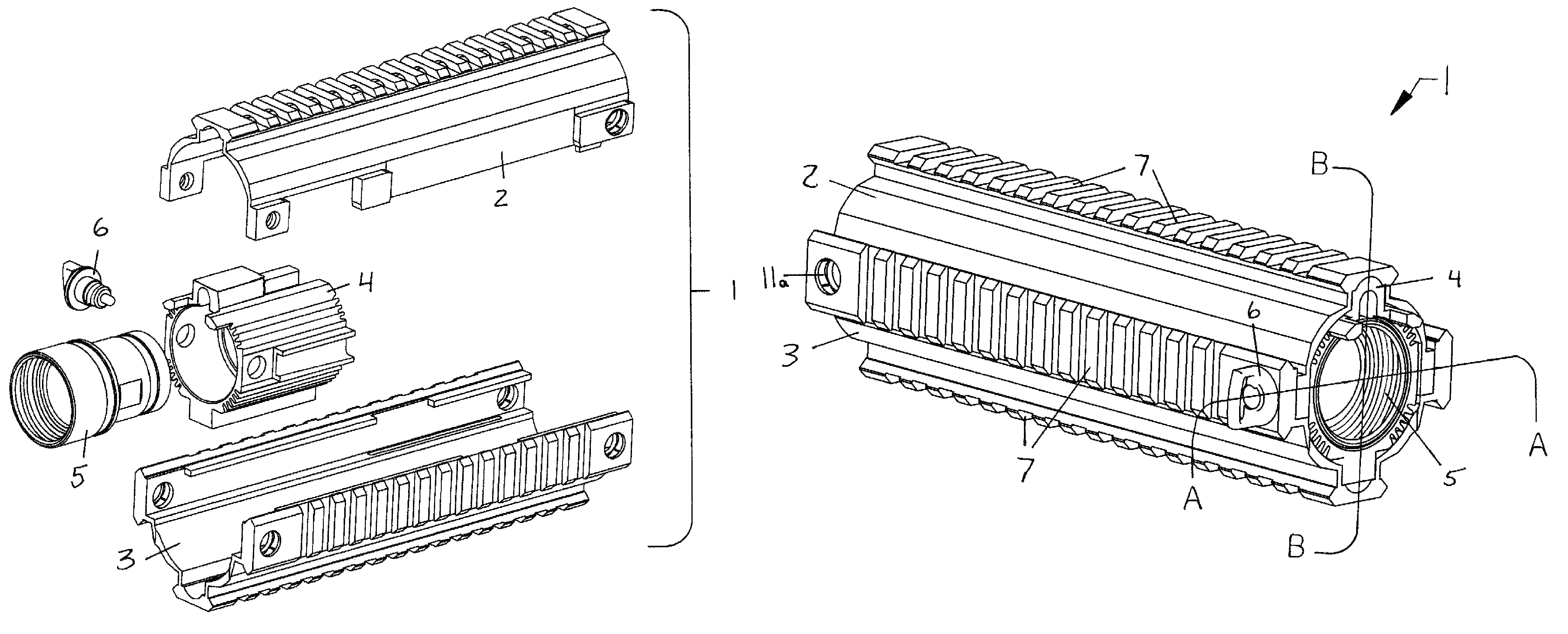
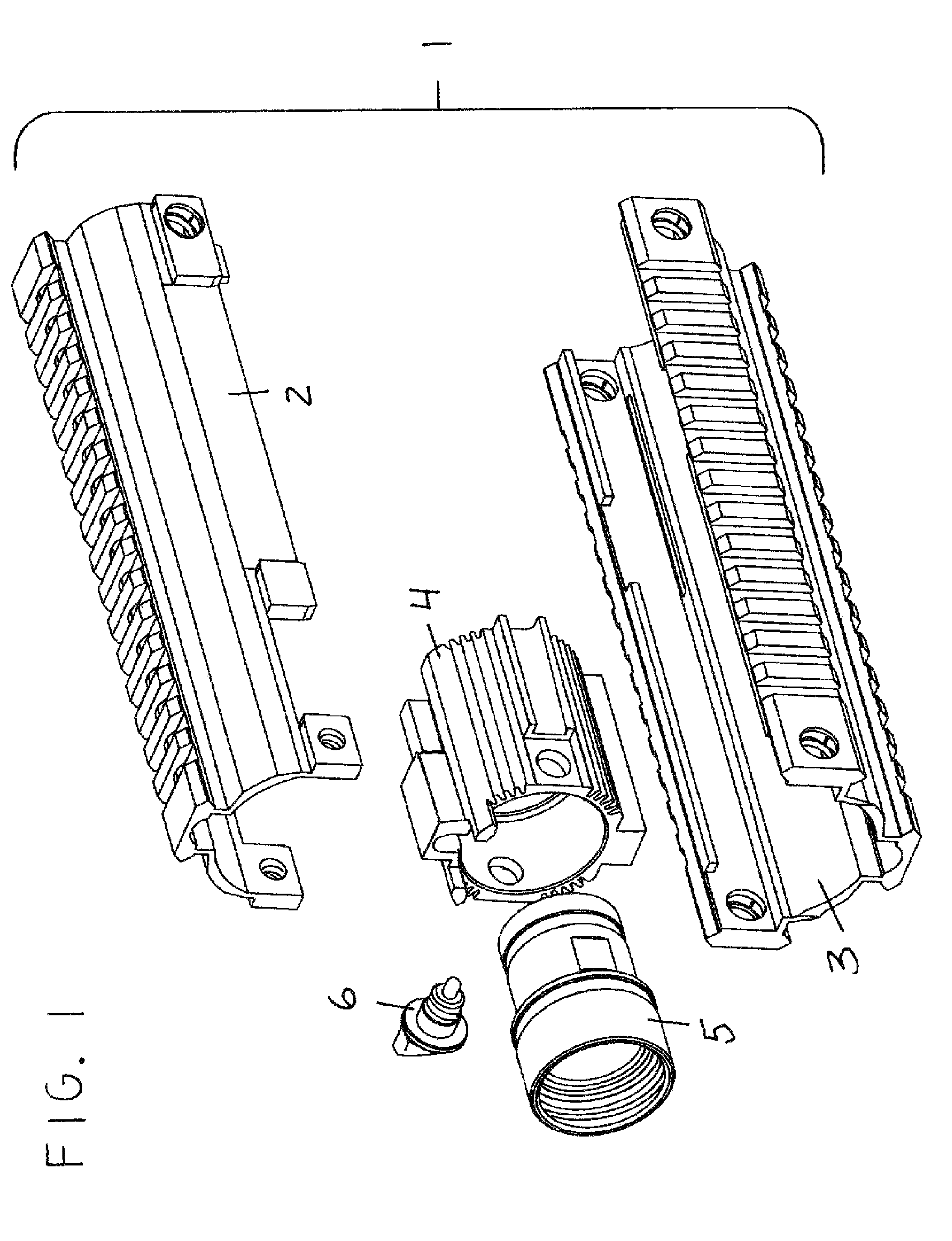
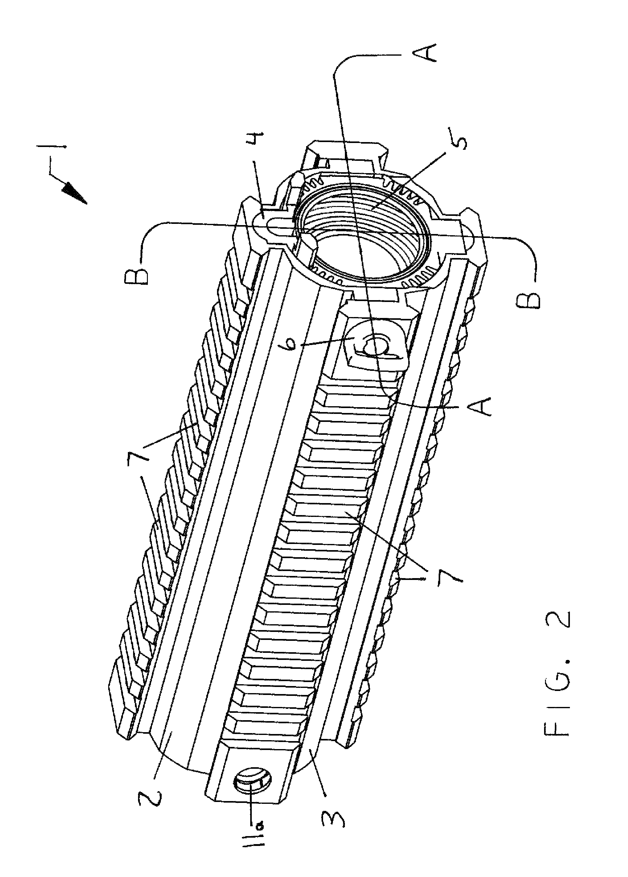
[0050]While FIG. 2 shows external structure of first preferred embodiment 1, FIGS. 3-6 illustrate internal structure that allows top hand guard element 2 and bottom hand guard element 3 to remain securely connected to one another while supported by outer barrel nut 4 in a laterally-stable cantilevered fashion. FIGS. 3 and 4 show outer barrel nut 4 positioned within the joined top hand guard element 2 and bottom hand guard element 3, with inner barrel nut 5 concentrically positioned within outer barrel nut 4. FIG. 3 also shows a spring-loaded detent screw 6 engaged with one sling swivel recess 11 (each having a rotation limiter and threads) that is located on the receiver end of top hand guard element 2 to tightly secure top and bottom hand guard elements together, and at the same time put pressure on both sides of the present invention hand guard due to the fact that the tip 25 of the spring-loaded detent screw 6 contacts the exterior surface of inner barrel nut 5 pushing away from ...

embodiment 26

[0057]FIGS. 25-27 show enlarged views of the hinged outer barrel nut 4′ used as a part of the second preferred embodiment 26 of the present invention. FIGS. 25 and 26 show outer barrel nut 4′ in a closed (or nearly closed) configuration, while FIG. 27 shows outer barrel nut 4′ in an opened configuration and ready for positioning around inner barrel nut 5′. FIG. 25 is a perspective view of the left side of hinged outer barrel nut 4′ showing one of its laterally-extending side lugs 21 (the opposed side lug 21 is hidden), spaced-apart tabs 22 on its left-facing (receiver) end 42 used for receiver 45 engagement, two opposed non-threaded holes 11b that become aligned with the sling swivel recesses 11 (each having rotation limiters and threads) on the receiver end of the top hand guard element 2 and which are used for insertion of a spring-loaded detent screw 6 so that its tip 25 can become engaged with the outer surface of inner barrel nut 5′, radially-extending baffles 20 used for heat ...


PUM


Abstract

A quick-detach, free floating, two-piece forward hand guard assembly for a rifle, which includes an inner barrel nut adapted for connection to the rifle's receiver and an outer barrel nut telescopically received over the inner barrel nut and secured thereto to prevent rotation therebetween. The hand guard assembly also includes a top hand guard element engaged with and extending forwardly from the outer barrel nut in a laterally-stable cantilevered orientation above the rifle's barrel. A bottom hand guard element is matingly engaged with the top hand guard element for surrounding the bottom portion of the rifle's barrel and free-floats from the top hand guard element. A spring-loaded detent screw attaches the top and bottom hand guard elements together and also engages the inner barrel nut. For quick-detach barrel removal, the outer barrel nut may be hinged for clamshell action, with the inner barrel nut having a separable two-piece extension.

Description

CROSS-REFERENCES TO RELATED APPLICATIONS[0001]This application is a Continuation-In-Part of a currently pending U.S. utility patent application for similar subject matter, which has the application Ser. No. 13 / 106,357, a Filing Date of May 12, 2011, and the Title of ‘Quick Release Hand Guard Assembly for a Rifle’. U.S. utility patent application Ser. No. 13 / 106,357 was filed by Kennneth F. Lupson, a business partner of the actual inventor and applicant herein, Brendon B. Zinsnser. Kennneth F. Lupson was the President of the jointly owned business and through a misunderstanding he hired attorneys to file U.S. utility patent application Ser. No. 13 / 106,357 in his own name, not in the name of the actual inventor, Brendon B. Zinsnser. A Request to Correct Inventorship under 37 CFR 1.48(a) was filed on Oct. 31, 2012, and in part included the following statement by Brendon B. Zinsner: “I am the actual inventor of the Quick Release Hand Guard Assembly for a Rifle that is disclosed in the a...

Claims


Application Information

Patent Timeline
IPC IPC(8): F41C23/16
CPCF41C23/16
Inventor ZINSNER, BRENDON, B.
Owner ZINSNER BRENDON B
Why Eureka
Try Eureka