Roller bearing and cage for a roller bearing

a roller bearing and cage technology, applied in the direction of mechanical equipment, engine components, rotary machine parts, etc., can solve the problems of complex and/or burdensome assembly process, substantially more costly final assembly of bearings, etc., to facilitate and/or simplify the assembly process, the effect of facilitating and/or simplifying the assembly process

Active Publication Date: 2014-10-21
AB SKF
View PDF43 Cites 3 Cited by
  • Summary
  • Abstract
  • Description
  • Claims
  • Application Information

AI Technical Summary

Benefits of technology

[0013]One aspect of the present teachings is based upon the recognition that the disadvantages of the known ring-guided cages can be overcome by providing a retaining rim (or retaining flange), which is affixed to the cage. In such embodiments of the present teachings, the roller bodies can be reliably prevented from falling out during the assembly of the bearing.
[0014]In another supplemental aspect of the present teachings, the retaining rim is preferably affixed on or to an axial end of the cage. In such embodiments of the present teachings, the insertion of the roller bodies, for example the balls, during the assembly of the bearing can be further simplified.
[0015]The present teachings can be utilized to provide a cost-effective system for assembling a ring-guided (not snap-type) cage, as well as to provide a cage design that is capable of receiving (retaining) a maximum number of roller bodies in the bearing.
[0016]In another aspect of the present teachings, the assembly of an angular contact ball bearing can be facilitated and / or simplified. In such embodiments of the present teachings, a cage may be provided, e.g., for a two-row angular contact ball bearing. In this aspect of the present teachings, a ring-guided cage is redesigned (as compared to the known art) so that its assembly process can be significantly simplified. This may be achieved by disposing a retaining rim on a side of one or more pockets at least around a portion of the circumference of the cage. More preferably, a retaining rim is associated with every pocket of the cage and thus retaining rims are provided around the entire circumference of the cage. In this aspect of the present teachings, the retaining rim represents a guiding-in means for inserting the roller bodies (e.g., balls) into the pockets of the cage. The insertion of the roller bodies is preferably achieved by redirecting the usual axial ball insertion direction into a combined axial / radial insertion direction. Furthermore, it is possible to prevent the roller bodies (e.g., balls) from inadvertently falling out of the pockets during the subsequent assembly steps of the bearing, in particular when the second ring is mounted on the combined first ring and cage with the roller bodies disposed therein.

Problems solved by technology

However, the roller bodies are not held by the cage, so that the final assembly of the bearing must be carried out in a substantially more costly manner, because the risk of the roller bodies falling out during the final ring mounting step exists.
However, the disadvantage is that the roller bodies (e.g., balls) can not be retained by the cage during the assembly process, which makes the assembly process more complicated and / or burdensome.

Method used


Image

  • Roller bearing and cage for a roller bearing
  • Roller bearing and cage for a roller bearing
  • Roller bearing and cage for a roller bearing

Examples


Embodiment Construction

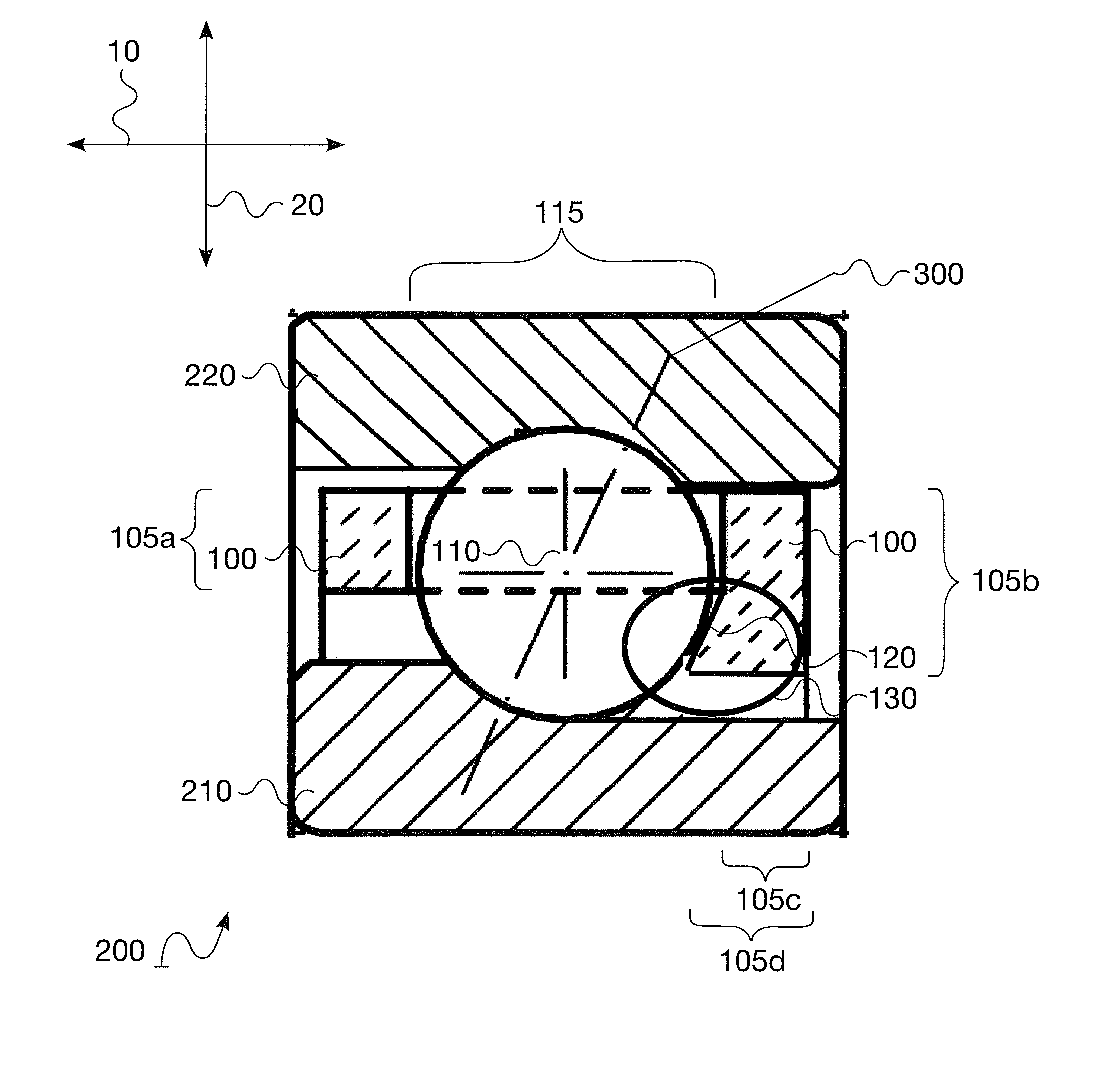
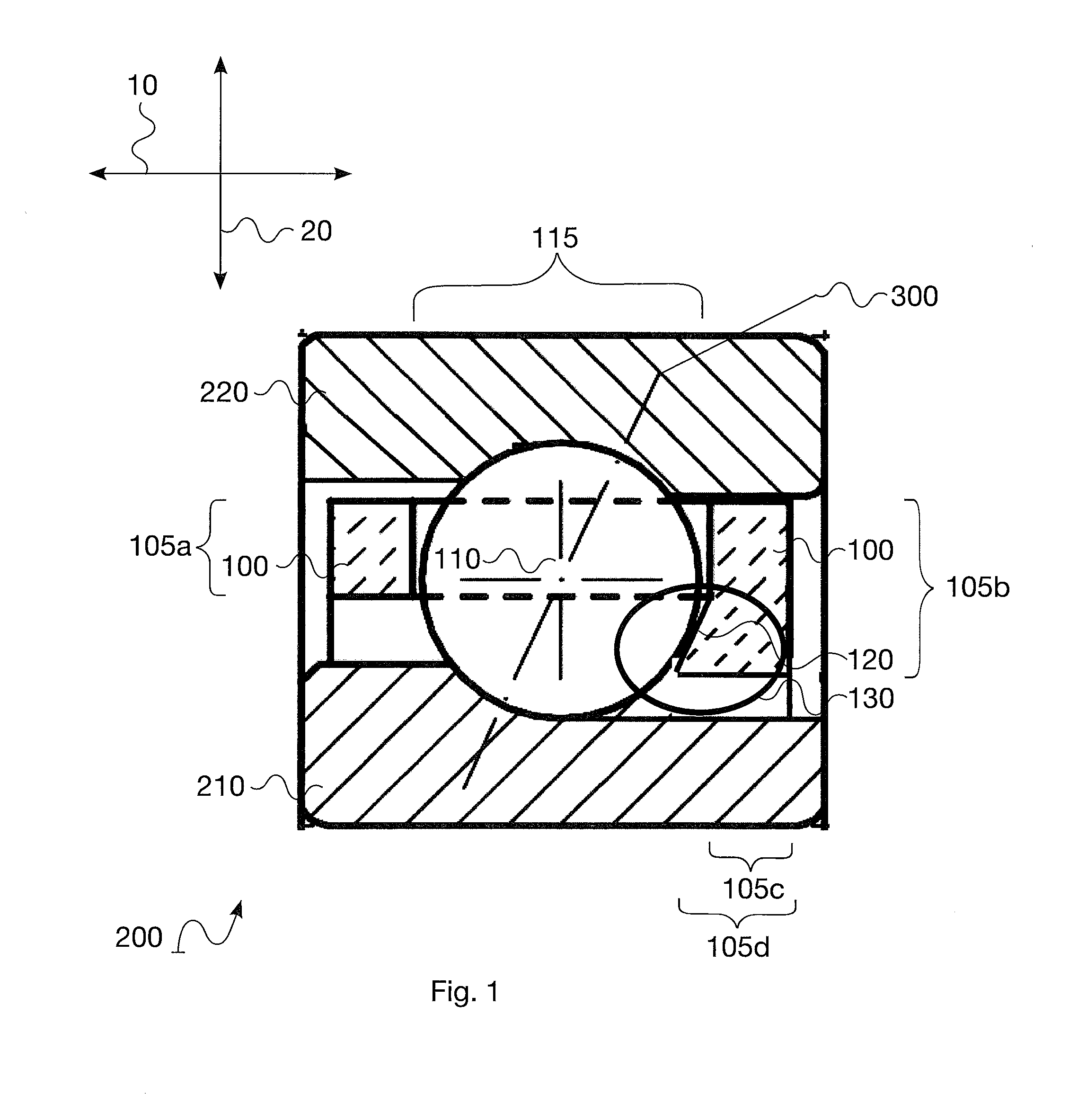
[0022]FIG. 1 shows an exemplary embodiment of a roller bearing 200 according to the present teachings.

[0023]The roller bearing 200 comprises an inner ring 210 and an outer ring 220. In the representative embodiment of FIG. 1, the roller bearing 200 is designed as an angular contact ball bearing and a diagonal roller body contact axis 300 is shown. However, as will be readily understood by persons of ordinary skill in the art after considering the following description and the appended drawings, the present teachings may be utilized with a variety of roller bearings, such as other types of ball bearings, cylindrical bearings, spherical bearings, tapered roller bearings, etc. The present teachings are not particularly limited in this regard. Also, the cage 100 may be made of metal, e.g., brass, steel, bronze, copper, etc. or may be made of a generally rigid polymer material, e.g., polyamide.

[0024]For the sake of clarity, only one roller body 110 is shown in the drawings, although it i...


PUM

PropertyMeasurementUnit
diametersaaaaaaaaaa
diameteraaaaaaaaaa
plastic deformationaaaaaaaaaa

Abstract

A roller bearing comprises an inner ring, an outer ring and an annular cage. The annular cage retains and guides at least one roller body. The annular cage comprises at least one pocket for retaining the roller body and at least one retaining rim disposed on one axial end of the pocket. The retaining rim extends at least in the radial direction relative to a main body of the cage.

Description

CROSS-REFERENCE[0001]The present application claims priority to German patent application no. 10 2010 062 479.9 filed on Dec. 6, 2010, the contents of which are incorporated herein by reference as if fully set forth herein.TECHNICAL FIELD[0002]The present invention relates to a roller bearing and a cage for a roller bearing, such as an angular contact ball bearing and a cage for an annular contact ball bearing.BACKGROUND ART[0003]As is illustrated in the cross-sectional view of an annular contact ball bearing shown in FIG. 3, known roller bearings 350 are typically comprised of an inner ring 360, an outer ring 370 and roller bodies 390. The roller bodies, e.g., balls, cones, cylinders, etc., are guided by a cage 380. In the following, ball bearings will be discussed as a representative example of the prior art.[0004]FIG. 3 further shows the roller bearing 350 designed as an annular contact ball bearing, which is indicated by the diagonal axis 400. The cage 380 includes openings or p...

Claims


Application Information

Patent Timeline
Patent Type & Authority Patents(United States)
IPC IPC(8): F16C33/38F16C19/16B21D53/12F16C19/06F16C43/06
CPCF16C43/06F16C33/3887F16C19/163B21D53/12F16C33/3843Y10T29/49691Y10T29/49643F16C2300/02F16C2240/40
Inventor GHILBERT-SIMON, AURELIENHAUCK, HELMUTHEEGE, THOMASHERBST, HUBERTKAMM, SANDRA
Owner AB SKF
Why Eureka
Try Eureka