Electrical current managing system

a technology of managing system and current, applied in the direction of electric generator control, process and machine control, instruments, etc., can solve the problems of circuit output load opening, electronic and electrical circuit output load being often subject to sudden in-rush of current, etc., to eliminate high in-rush of current and large load

Active Publication Date: 2014-10-21
WRIGHT SHAWN P
View PDF10 Cites 7 Cited by
  • Summary
  • Abstract
  • Description
  • Claims
  • Application Information

AI Technical Summary

Benefits of technology

[0014]When the system activation signal is applied to the ECC, the ECMS becomes operational, thereby allowing the combination of the ECC and the SCR to produce a phase controlled voltage that ramps upward from zero volts to full power over a two to three second time period. The ramped voltage prevents a sudden in-rush of current to be applied to the output load, conversely when the system activation signal is not applied, the ECC produces a relay activation signal. The relay activation signal is applied to the coil of the power control relay which energizes the relay, allowing the relay contacts to open causing said output load to disconnect.
[0015]The ECMS utilizes “phase control” to set the maximum current draw of the inductive and / or dynamic load. The ECMS also features a “soft start” that ramps the output current “on” and “off” from zero to full current over approximately a two second time period. The “soft start” feature eliminates high in-rush of current or power surges from being applied to a system distribution panel or master breaker, thereby allowing a larger load to be installed than would otherwise be possible. The ECMS via the ECC, also utilizes an SCR “fault detection” circuit that opens the power control relay and turns it off in the event the SCR fails or when the ECMS is “off” and the load attempts to stay “on”.
[0020]eliminates the need to install “overrated” circuit breakers and servicing long run conductors,
[0021]reduces electrical consumption by establishing and controlling the upper current limit,
[0023]allows a larger load to be installed on a given circuit breaker and conductor combination, and

Problems solved by technology

The output load on electronic and electrical circuits is often subjected to a sudden in-rush of current when the circuit is initially turned on.
This in-rush of current, can in many cases, cause a circuit output load to open if the circuit is not protected.
Rather they fail when the sudden in-rush of current is applied to the light bulb filament when the light bulb is initially turned “on” by a conventional power switch.

Method used


Image

  • Electrical current managing system
  • Electrical current managing system

Examples


Embodiment Construction

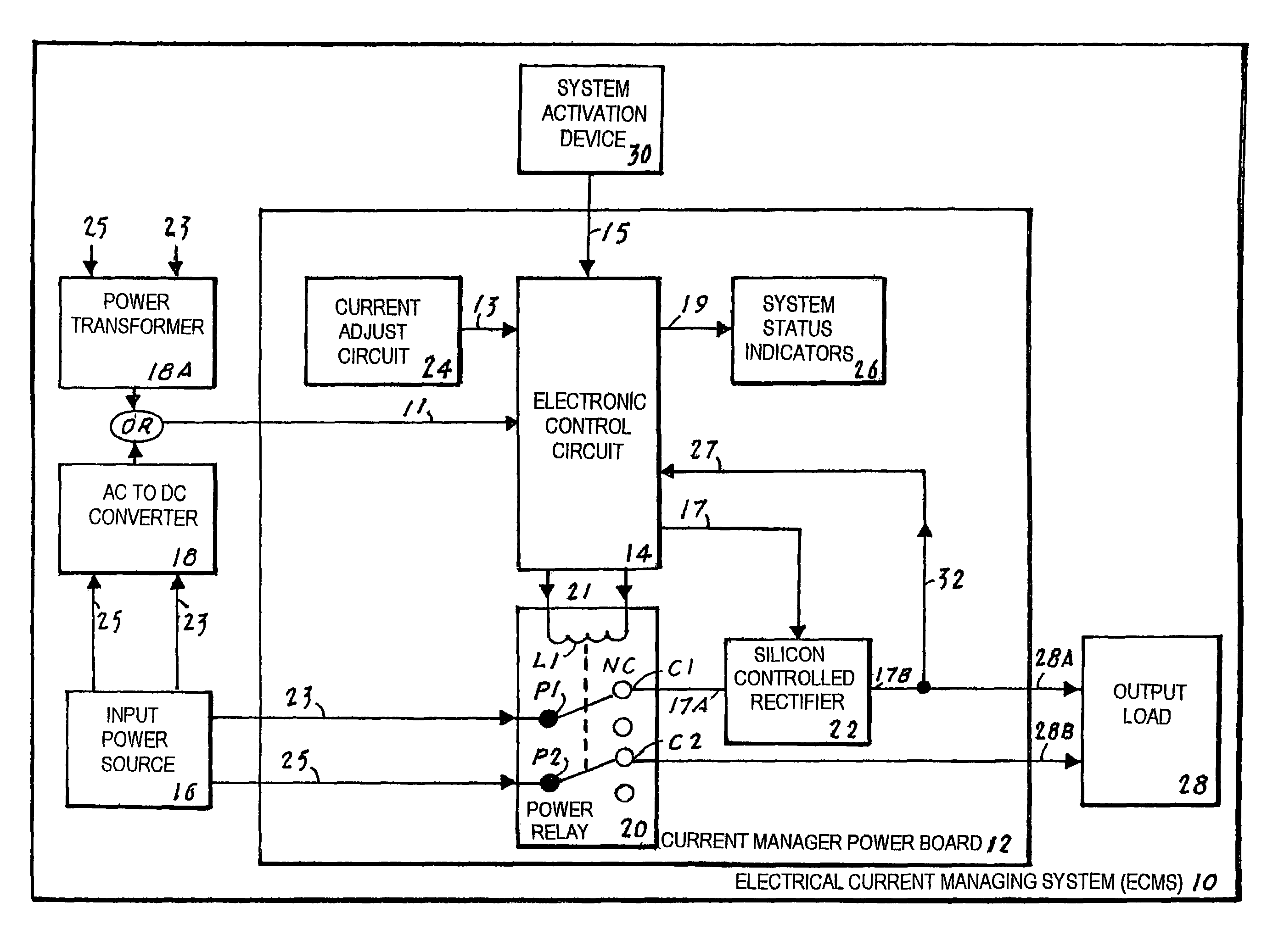
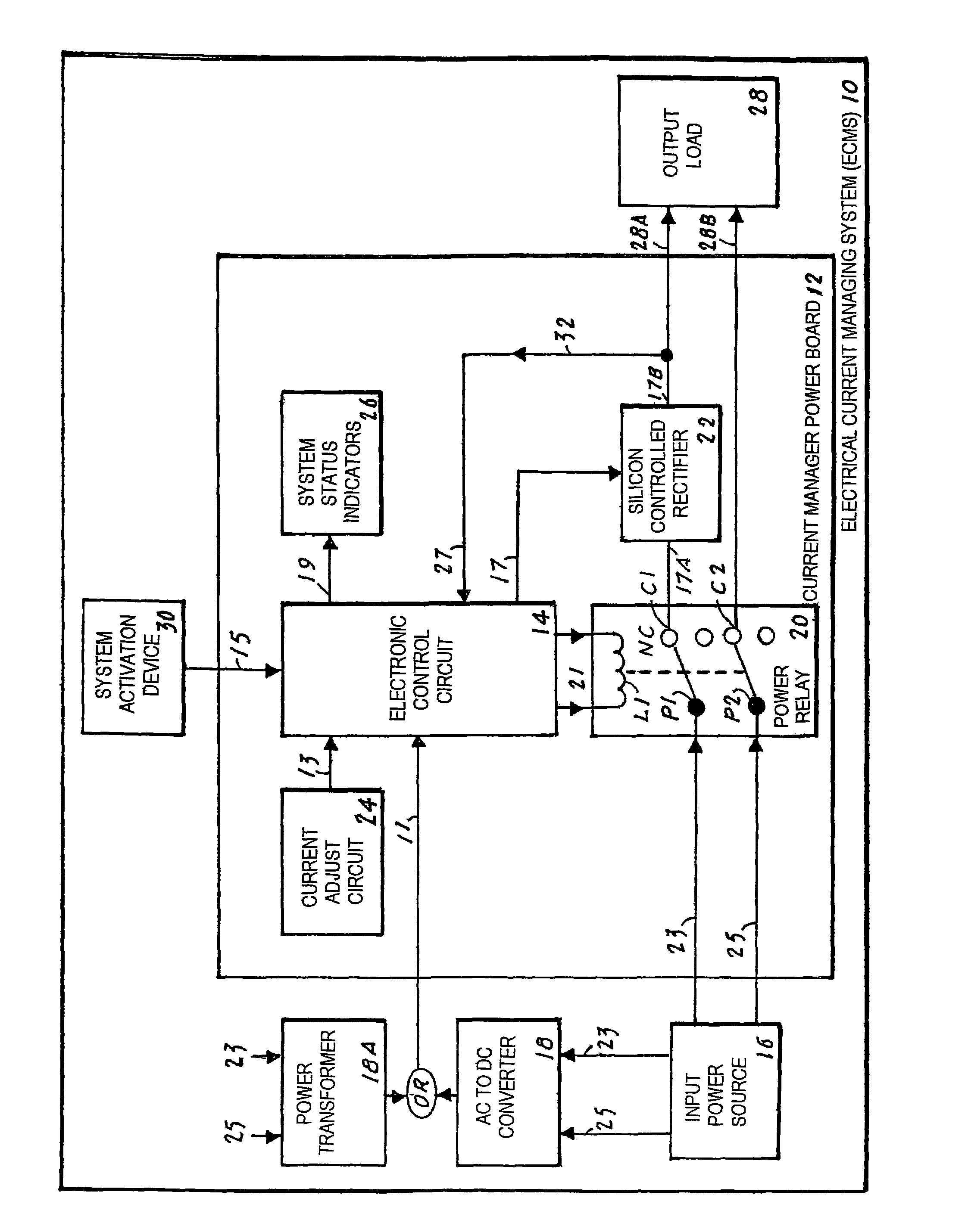
[0027]The best mode for carrying out the invention is presented in terms that disclose a preferred embodiment of an electrical current managing system (ECMS) 10. The ECMS 10, which is also referred to as THE CURRENT MASTER™, is designed to utilize a soft current start in combination with “phase control” to set the maximum current draw of an inductive and / or a dynamic load.

[0028]The preferred embodiment of the ECMS 10, as shown in FIG. 1, is comprised of the following elements that are attached to a current manager power circuit board 12: an electronic control circuit (ECC) 14, a power control relay 20, a silicon controlled rectifier (SCR) 22, a current adjust circuit 24, a set of system status indicators 26 and a feedback loop 32. The above circuit board-attached elements function in combination with the following circuit board-external elements: an input power source 16, an AC to DC converter 18 or a power transformer 18A, a system activating device 30 and an output load 28.

[0029]T...


PUM


Abstract

An electronic current managing system (ECMS) (10) that utilizes “phase control” to set the maximum current draw of an output load (28) that can consist of an inductive or a dynamic load. The ECMS (10) features a “soft start” that ramps the electric current from zero to full current over a two second period of time. The “soft start” eliminates high in-rush current or power surges from being applied to a system distribution panel or master breaker, thereby allowing a larger output load (28) than would otherwise be possible. The ECMS (10) includes an SCR (22) that causes a power control relay (20) to close or to open in the event the SCR (22) fails and the output load (28) attempts to stay “on”. An example of an ECMS (10) output load (28) is a self regulating cable which has a high in-rush current draw that is approximately three times the rated current per watt.

Description

TECHNICAL FIELD[0001]The invention generally pertains to electrical current control systems, and more particularly to an electrical current managing system (ECMS) that applies a phase controlled, soft current start to an inductive or a dynamic loadBACKGROUND ART[0002]The output load on electronic and electrical circuits is often subjected to a sudden in-rush of current when the circuit is initially turned on. This in-rush of current, can in many cases, cause a circuit output load to open if the circuit is not protected. An example of this potential hazard can be likened to a typical household light bulb dimmer that applies power to the filament of an incondescent light bulb. The dimmer is operated from an “off” position to full brightness over a two to three second time period. This upward-ramped input voltage prevents the initial in-rush of current to be applied to the filament of the light bulb.[0003]Light bulbs seldom fail after they are turned on and have been illuminating over ...

Claims


Application Information

Patent Timeline
Patent Type & Authority Patents(United States)
IPC IPC(8): H02H1/04
CPCH02H1/043
Inventor WRIGHT, SHAWN, P.
Owner WRIGHT SHAWN P
Why Eureka
Try Eureka