
PMSM field weakening for appliance motors

a technology of synchronous machine and appliance motor, which is applied in the field of electric motors, can solve the problems of significant micro-processor resources, inefficient implementation of this technique, and computational speed

Active Publication Date: 2014-10-21
HAIER US APPLIANCE SOLUTIONS INC
View PDF14 Cites 13 Cited by
  • Summary
  • Abstract
  • Description
  • Claims
  • Application Information

AI Technical Summary

Benefits of technology

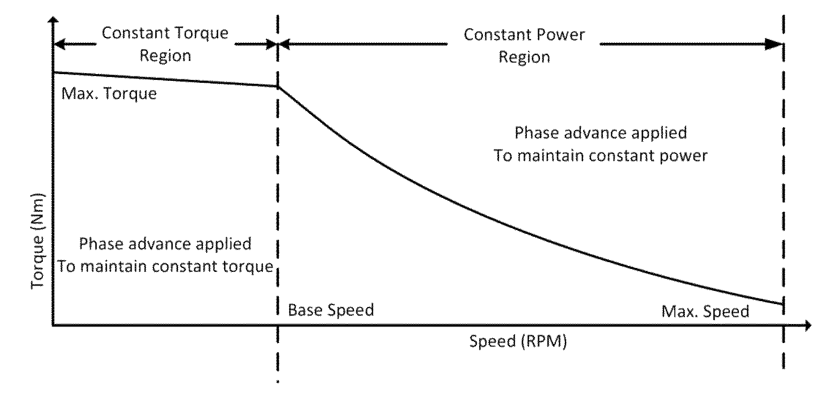
The patent describes a motor drive system that uses a field weakening technique to operate a motor at a desired speed. This technique involves applying a power signal to the motor with a specific phase angle and adjusting the amplitude of the signal based on the motor's speed. The system includes an inverter and a controller for driving the motor. The technical effects of this invention include improved control of motor speed, simplified circuit design, and reduced noise in the motor's operation.

Problems solved by technology

However, the implementation of this technique is inefficient due to limited memory space in the micro-processor and a reduction in computational speed.
This calculation requires significant micro-processor resources and leads to complexity of the system.

Method used


Image

  • PMSM field weakening for appliance motors
  • PMSM field weakening for appliance motors
  • PMSM field weakening for appliance motors

Examples


Embodiment Construction

[0022]Reference now will be made in detail to embodiments of the invention, one or more examples of which are illustrated in the drawings. Each example is provided by way of explanation of the invention, not limitation of the invention. In fact, it will be apparent to those skilled in the art that various modifications and variations can be made in the present invention without departing from the scope or spirit of the invention. For instance, features illustrated or described as part of one embodiment can be used with another embodiment to yield a still further embodiment. Thus, it is intended that the present invention covers such modifications and variations as come within the scope of the appended claims and their equivalents.

[0023]Generally, the present disclosure relates to an electric motor in an appliance and a method of controlling the motor to achieve speeds greater than a base speed of the motor. The base speed of the motor is the maximum speed the motor can reach without...


PUM


Abstract

An electric motor in an appliance and a method of controlling the motor to achieve speeds greater than a base speed of the motor is provided. To achieve speeds above the base speed of the motor, field weakening can be implemented by applying a field weakening angle to a phase advance angle between a desired stator flux and a rotor flux. The field weakening angle can be based on the current speed of the motor. The field weakening angle can be a fixed angle and can be determined by comparing the current speed of the motor with a predetermined threshold. In addition, the magnitude of the electrical signal applied to the motor can be adjusted during field weakening based on a desired speed of the motor where the electrical signal can be a voltage.

Description

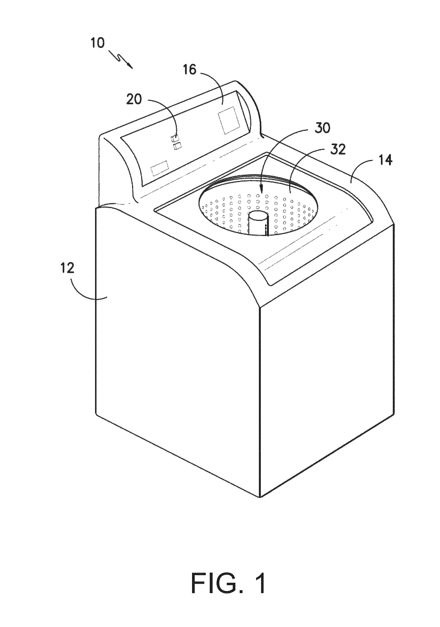
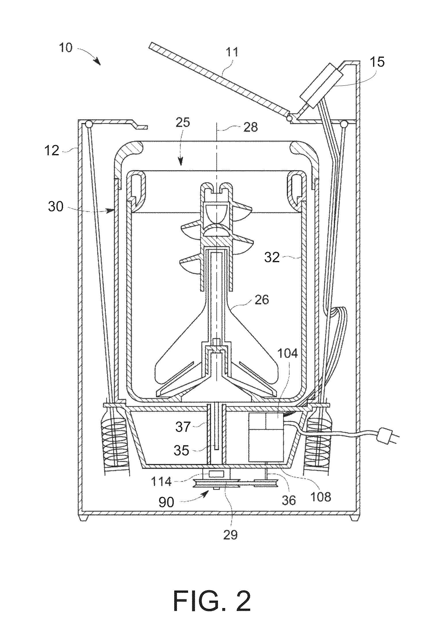
FIELD OF THE INVENTION[0001]The present disclosure relates to an electric motor, and more particularly to a system and method of controlling a permanent magnet synchronous machine (PMSM) motor.BACKGROUND OF THE INVENTION[0002]Motors are used in various appliances to convert electrical power into mechanical energy to produce actuation about an axis. For example, in a washing machine a motor can be coupled with a washing tub such that the tub rotates at various speeds. In an air conditioner, a motor can be coupled with a fan to circulate air. In a refrigerator, a motor can be coupled with a compressor to supply cool air into a fresh food and / or freezer compartment.[0003]A permanent magnet synchronous machine (PMSM) motor can include a rotor having a permanent magnet and a stator having a plurality of electromagnetic poles such that the rotor rotates about an axis by locking into the rotating magnetic fields generated on the stator. In a PMSM motor, base speed is the maximum speed the ...

Claims


Application Information

Patent Timeline
Patent Type & Authority Patents(United States)
IPC IPC(8): H02P6/08
CPCH02P23/009H02P2205/07H02P23/14
Inventor SUEL, II, RICHARD D.BHANDWALE, ABHIJEET A.
Owner HAIER US APPLIANCE SOLUTIONS INC
Learn More