Hybrid drive for helicopters

a hybrid drive and helicopter technology, applied in the direction of efficient propulsion technology, power plant type, transportation and packaging, etc., can solve the problems of low drive system efficiency and loud drive of the current helicopter

Active Publication Date: 2014-10-28
AIRBUS HELICOPTERS DEUT GMBH +1
View PDF87 Cites 21 Cited by
  • Summary
  • Abstract
  • Description
  • Claims
  • Application Information

AI Technical Summary

Benefits of technology

[0008]For example, the speed of the main rotor (and / or tail rotor) can be set within a large interval in this way. In this way, the highly variable speed of the rotor makes it possible to optimize the energy consumption. As a result, the performance and emission of the helicopter can be optimized. Because the rotor is directly powered, additional mechanical elements, such as a clutch or wobble plate, can be simplified in design or omitted entirely.
[0015]In another embodiment of the invention, the second motor is designed for directly powering the rotor, so that no rotor gearbox is required. Mechanical elements can be eliminated in this way, making it possible to reduce upkeep and maintenance costs, and increase energy efficiency.
[0016]In another embodiment of the invention, the first motor and the generator are designed for space-saving installation, e.g., under a cabin floor of the helicopter. In this way, the center of gravity can be shifted downward, thereby elevating the stability of the helicopter on the ground (e.g., during autorotation landings). The safety of passengers during crash landings is also improved by the absence of large masses in the cabin canopy area.
[0018]In another embodiment of the invention, the mounting device is designed as a tilting mounting device with a tilting bearing and tilting actuator. This makes it possible to tilt the motor and rotor together around an axis. For example, this axis can be an axis situated transverse to the longitudinal axis of the helicopter, so that the motor and rotor can be tilted toward the front and back.
[0020]The mounting device can further be designed as a gimbaled mounting device. This makes it possible to tilt the rotor in all directions.
[0021]It can also be provided that the mounting device is designed to generate a specific oscillation mode of the electric motor in such a way that an inversely phased oscillation can be generated, which is able to extinguish an original oscillation. This makes it possible to compensate for undesired vibrations.

Problems solved by technology

Contemporary helicopters often exhibit a low efficiency of the drive system.
In addition, the drive is often very loud.

Method used


Image

  • Hybrid drive for helicopters
  • Hybrid drive for helicopters
  • Hybrid drive for helicopters

Examples


Embodiment Construction

[0036]The depictions in the figures are schematic and not to scale.

[0037]The same reference numbers are used in the following description of figures for identical or similar elements.

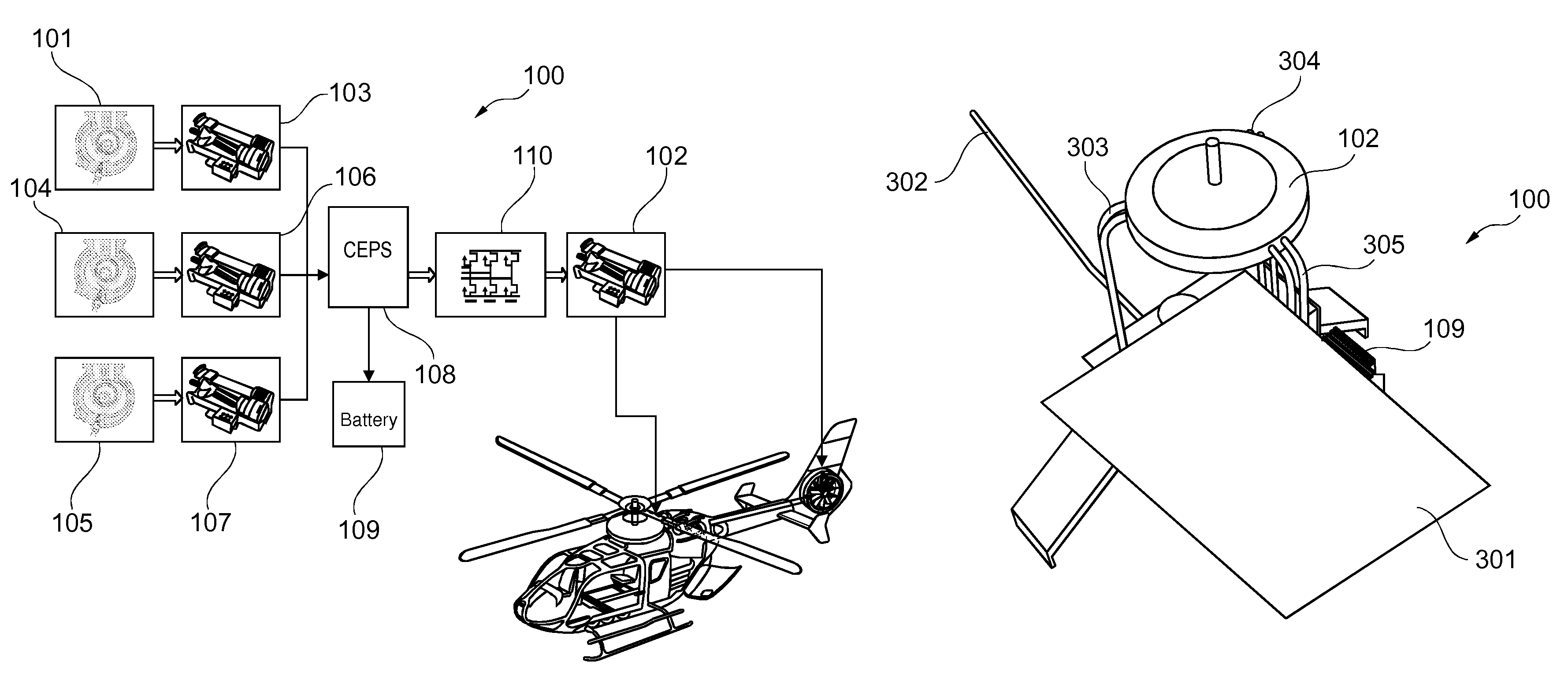
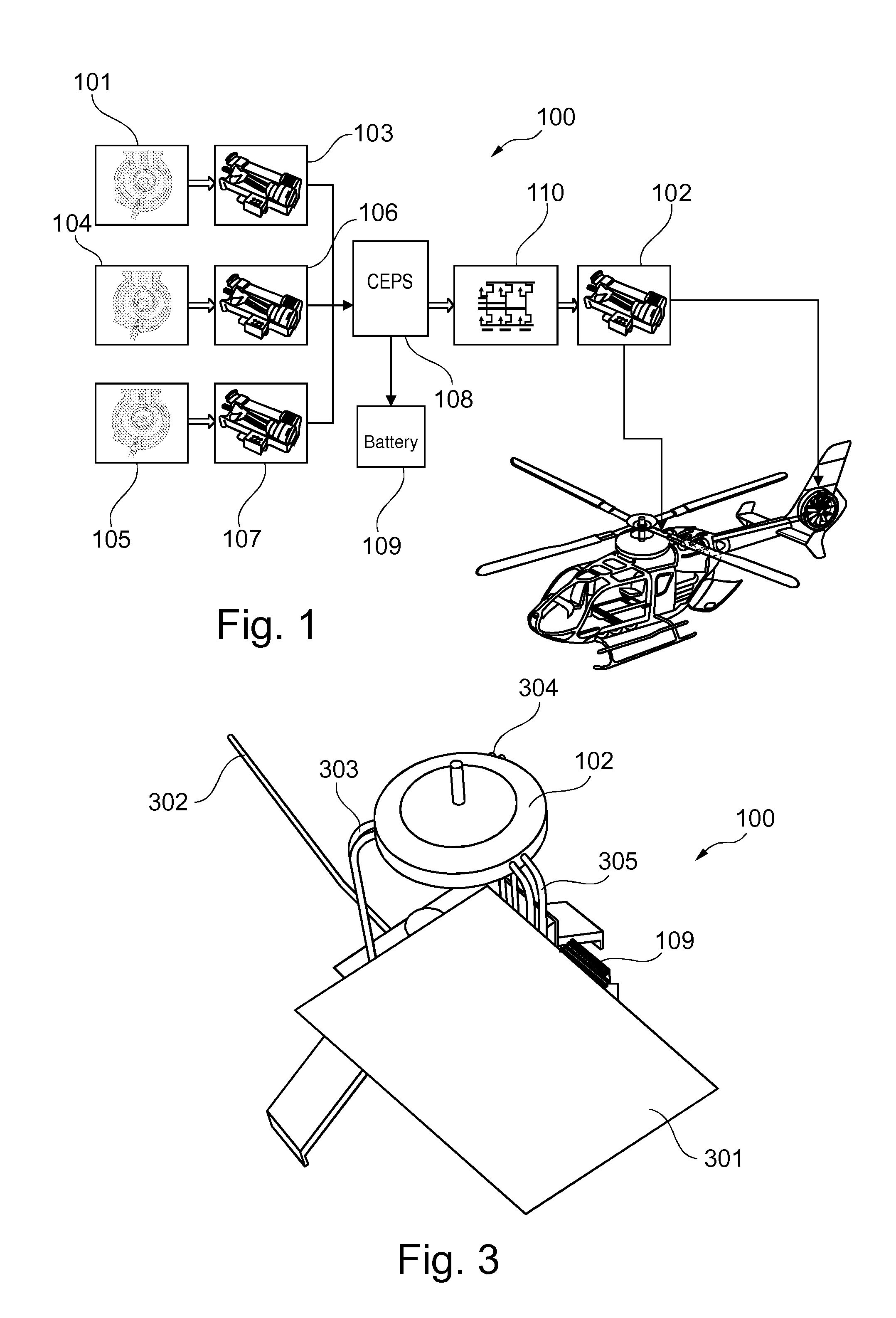
[0038]FIG. 1 shows a hybrid drive for a helicopter according to an embodiment of the invention. The hybrid drive 100 of the helicopter comprises one or more internal combustion engines (three internal combustion engines 101, 104, 105 in the embodiment on FIG. 1) and one or more electric generators (three generators 103, 106, 107 in the embodiment on FIG. 1). Each internal combustion engine releases mechanical energy to the corresponding generator, which is then converted into electrical energy. This electrical energy is then released to a central energy control system (“central electrical power system”, CEPS) 108, which handles power control operations in the helicopter. As a result, the electrical energy can be released to an inverter 110, which supplies the electric motor(s) 102 with the necessary ele...


PUM


Abstract

The rotors of a helicopter are powered by electric motors. The electrical energy required for this purpose is produced by a motor-generator unit, which comprises one or more internal combustion engines. The motor-generator unit can be secured under the cabin floor. This yields a hybrid helicopter that can set the rotational frequency of the rotors within a large interval.

Description

CROSS-REFERENCE TO RELATED APPLICATIONS[0001]The present application is a continuation of International Application No. PCT / EP2011 / 058123, filed May 19, 2011, which claims priority from German Application No. 10 2010 021 025.0, filed May 19, 2010, the disclosures of which are incorporated herein by reference.FIELD OF THE INVENTION[0002]The invention relates to helicopter drives. In particular, the invention relates to a hybrid drive for a helicopter, the use of a hybrid drive in a helicopter, a hybrid helicopter as well as a method for powering a main rotor and / or a tail rotor of a helicopter.BACKGROUND OF THE INVENTION[0003]Contemporary helicopters often exhibit a low efficiency of the drive system. In addition, the drive is often very loud.[0004]The drive train consists of one or more internal combustion engines and a mechanical main gear unit. Turbine shaft drives or reciprocating piston engines are frequently used.[0005]DE 10 2008 028 866 A1 as well as WO 2009 / 153236 A2 describe...

Claims


Application Information

Patent Timeline
Patent Type & Authority Patents(United States)
IPC IPC(8): B64D27/02B64D27/04B64C27/14B64C27/04B64D35/02B64D27/24B64D27/00
CPCB64D2027/026B64D27/04B64C27/14Y02T50/64B64D27/24B64D35/02B64C27/04Y10S903/903B60L2200/10B60L50/15Y02T10/7072Y02T50/60Y02T10/64
Inventor BOTTI, JEANSTUHLBERGER, JOHANNESJANKER, PETERKLOPPEL, VALENTINNIESL, GEORG
Owner AIRBUS HELICOPTERS DEUT GMBH
Why Eureka
Try Eureka