
Perpendicular magnetic recording medium

a magnetic recording medium and perpendicular technology, applied in the field of perpendicular magnetic recording medium, can solve the problems of increasing noise, increasing orientational dispersion, and reducing signal output, so as to reduce the effective film thickness of the non-magnetic intermediate layer, improve writability, and reduce the effect of medium nois

Inactive Publication Date: 2014-10-28
FUJI ELECTRIC CO LTD
View PDF32 Cites 0 Cited by
  • Summary
  • Abstract
  • Description
  • Claims
  • Application Information

AI Technical Summary

Benefits of technology

The invention provides a perpendicular magnetic recording medium that reduces film thickness of the underlayer or intermediate layer without reducing the magnetic characteristics of the magnetic recording layer, thereby improving performance such as reducing noise, increasing SNR, and improving writability. This is achieved by using a non-magnetic underlayer with a face-centered cubic, hexagonal close packing, or amorphous structure and a ferromagnetic intermediate layer. The invention simultaneously reduces medium noise, improves SNR, and improves writability by reducing the distance between the soft-magnetic underlayer and the magnetic head.

Problems solved by technology

One cause of a decrease in signal output and an increase in noise is an increase in the orientational dispersion (variation in crystal orientation) of the magnetic recording layer.
This is because, in the event that the crystal particle diameter of the magnetic recording layer increases, the bit transition region becomes irregular, and transition noise increases.
However, at present, the non-magnetic underlayer and / or intermediate layer has a film thickness of around 20 to 30 nm, and this large film thickness is a cause of increasing the distance between the soft-magnetic underlayer and the magnetic head.
However, it is known that, when reducing the film thickness of the underlayer or intermediate layer, a decrease in the crystal orientation of the magnetic recording layer material and a deterioration of magnetic isolation between magnetic crystal particles occur, and the magnetic characteristics of the magnetic recording layer decrease.

Method used


Image

  • Perpendicular magnetic recording medium
  • Perpendicular magnetic recording medium
  • Perpendicular magnetic recording medium

Examples


example 1

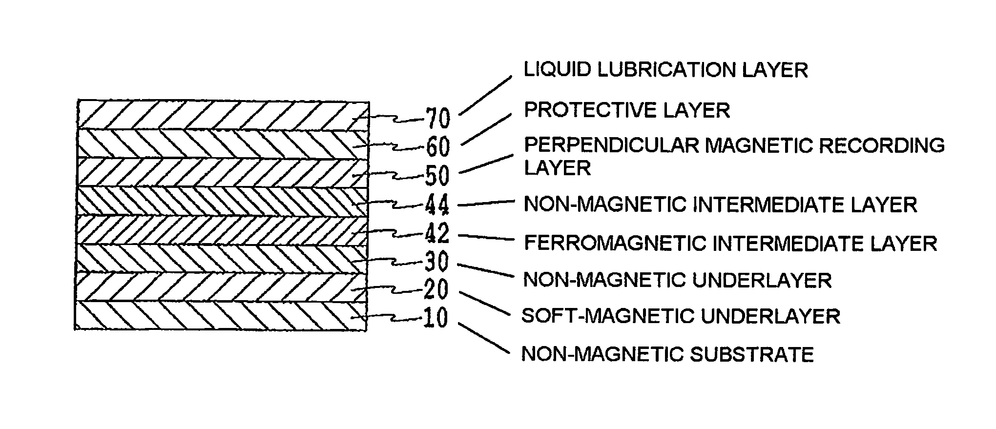
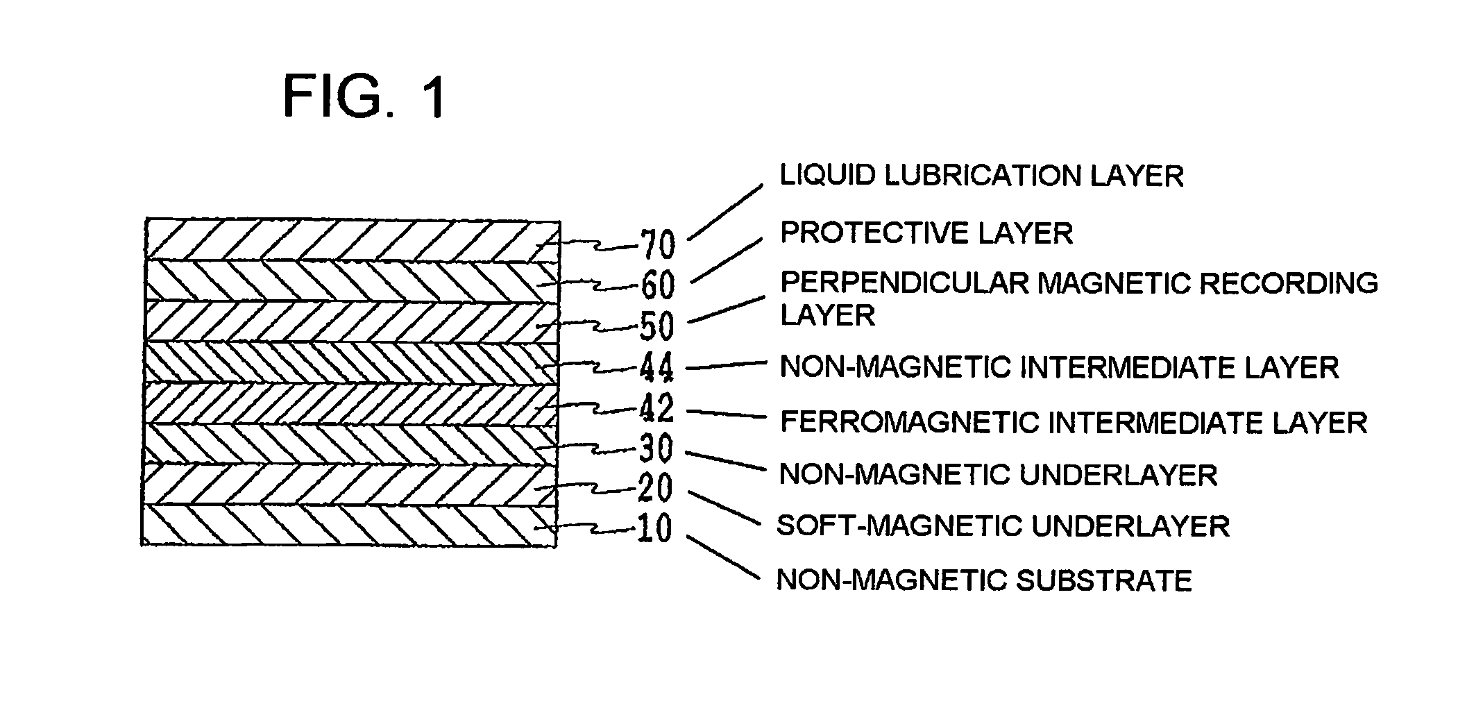
[0041]A chemically reinforced glass substrate with a smooth surface (a HOYA N-5 glass substrate) is cleaned, and used as the non-magnetic substrate 10. The non-magnetic substrate 10 is introduced into a DC magnetron sputtering device and, using a Co3Zr5Nb (configured of 3% Zr, 5% Nb, and the remainder Co, with the total number of atoms as a reference; the same applying hereafter) target in an Ar gas at a pressure of 0.67 Pa, the CoZrNb amorphous soft-magnetic underlayer 20 with a film thickness of 40 nm is deposited. Next, using a Ni25Cr target in an Ar gas at a pressure of 0.67 Pa, the Ni25Cr non-magnetic underlayer 30 with a film thickness of 6 nm is deposited. The Ni25Cr film obtained is non-magnetic, and has an fcc structure.

[0042]Next, using a Co25Cr target in an Ar-4% N2 gas at a pressure of 0.67 Pa, the Co25Cr ferromagnetic intermediate layer 42 with a film thickness of 2 nm is deposited. Herein, the saturation magnetic flux density Bs of the Co25Cr ferromagnetic intermediate...

examples 2 to 6

, Comparison Examples 1 and 2

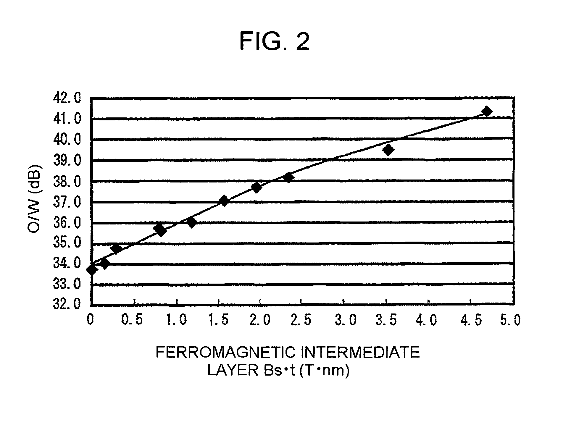
[0045]In each example, the total film thickness of the Co25Cr ferromagnetic intermediate layer 42 and the Co35Cr film which is the lower layer of the non-magnetic intermediate layer 44 is fixed at 12 nm. Except that the film thicknesses of the Co25Cr ferromagnetic intermediate layer 42 and Co35Cr film are changed as shown in Table 1, the perpendicular magnetic recording media are obtained by repeating the procedure of Example 1. The product Bs·t of the saturation magnetic flux density Bs and film thickness t of the Co25Cr ferromagnetic intermediate layer 42 is also shown in Table 1.

[0046]

TABLE 1Film thickness and Bs · t of ferromagnetic intermediatelayer 42, and film thickness of lower layer of non-magneticintermediate layer 44FerromagneticNon-magneticIntermediateIntermediate LayerFerromagneticLayer 42 (Co25Cr)44 Lower LayerIntermediateFilm Thickness(Co35Cr) FilmLayer 42 Bs · t(nm)Thickness (nm)(T · nm)Example 12100.78Example 2391.17Example 3481.56Exampl...

examples 7 to 9

[0047]In each example, except that (a) a ferromagnetic intermediate layer 42 configured of a CoCr alloy wherein the relative proportion of Cr is changed from 28% of the atoms to 32% of the atoms and having a film thickness of 12 nm is formed, and (b) the Co35Cr film of the lower layer of the non-magnetic intermediate layer 44 is omitted, and the non-magnetic intermediate layer 44 is made a single-layer film having a film thickness of 8 nm, the perpendicular magnetic recording media are obtained by repeating the procedure of Example 1. The composition of the CoCr ferromagnetic intermediate layer 42, the saturation magnetic flux density Bs, and the product Bs·t of the saturation magnetic flux density Bs and film thickness t are shown in Table 2.

[0048]

TABLE 2Composition of ferromagnetic intermediate layer 42,saturation magnetic flux density Bs, and Bs · tFerromagnetic IntermediateLayer 42 CharacteristicsSaturationMagnetic FluxCompositionDensity Bs (T)Bs · t (T · nm)Example 7Co28Cr0.068...


PUM

PropertyMeasurementUnit
thicknessaaaaaaaaaa
thicknessaaaaaaaaaa
thicknessaaaaaaaaaa

Abstract

A perpendicular magnetic recording medium includes at least a soft-magnetic underlayer, a non-magnetic underlayer, a ferromagnetic intermediate layer, a non-magnetic intermediate layer, and a perpendicular magnetic recording layer sequentially stacked on a non-magnetic substrate. In an embodiment, the ferromagnetic intermediate layer is formed of a CoCr based alloy, a product Bs·t of a saturation magnetic flux density and film thickness of the ferromagnetic intermediate layer is within a range of 0.15 to 3.6 T·nm, and the non-magnetic intermediate layer has a film thickness of 3 nm or more.

Description

BACKGROUND[0001]1. Technical Field[0002]The present invention relates to a perpendicular magnetic recording medium mounted in various kinds of magnetic recording devices. More particularly, the invention relates to a perpendicular magnetic recording medium mounted in a hard disc drive (HDD) used as an external storage device of a computer, audiovisual (AV) instrument, or the like.[0003]2. Related Art[0004]Since 1997, the recording density of a hard disk drive (HDD) has increased sharply at an annual rate of 60 to 100%. As a result of this kind of remarkable growth, an increase in density with the in-plane recording method used to date is nearing its limit. Given such circumstances, attention has focused in recent years on a perpendicular recording method whereby an increase in density is possible, and research into and development of the method has been vigorously pursued. Then, the long-awaited commercialization of an HDD employing the perpendicular recording method was started in ...

Claims


Application Information

Patent Timeline
Patent Type & Authority Patents(United States)
IPC IPC(8): G11B5/66G11B5/73G11B5/738
CPCG11B5/66G11B5/738G11B5/7325G11B5/7368G11B5/7377G11B5/7371G11B5/7373G11B5/676G11B5/678G11B5/672
Inventor KATO, HISATO
Owner FUJI ELECTRIC CO LTD
Learn More